Supercharge Your Innovation With Domain-Expert AI Agents!

Non-open excavation dismantling construction method for drilled underground structure

An underground structure and construction method technology, applied in building construction, building maintenance, construction and other directions, can solve the problems of long construction time, affecting traffic and environment, high demolition cost, short construction period, simple demolition construction method, and high demolition cost. low cost effect

Inactive Publication Date: 2018-02-27
NO 1 CONSTR ENG CO LTD OF CHINA CONSTR THIRD ENG BUREAU CO LTD
View PDF6 Cites 6 Cited by
  • Summary
  • Abstract
  • Description
  • Claims
  • Application Information

AI Technical Summary

Problems solved by technology

At present, the usual practice is to remove the original structures after open excavation and then backfill them. However, many of the structures to be removed are located at the lower part of the road, and the construction time of the underground structures will be long when they are removed, which will affect traffic and the environment, and the demolition cost is high.

Method used


Image

  • Non-open excavation dismantling construction method for drilled underground structure
  • Non-open excavation dismantling construction method for drilled underground structure
  • Non-open excavation dismantling construction method for drilled underground structure

Examples


Embodiment 1

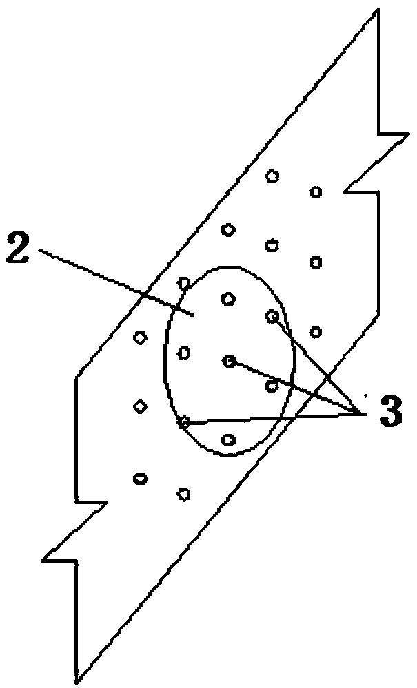
[0040] Embodiment one: if figure 1 As shown, the shield machine drills and crosses from the middle of culvert 1, and the specific removal method for the parts of the two sides of culvert 1 that are crossed by the shield machine is as follows:

[0041] Step 1. According to the drilling route of the shield machine, determine the specific position where both sides of the culvert 1 are crossed, that is, the position where the culvert body is crossed;

[0042] Step 2. Grouting to rock mass or soil mass

[0043] Grouting in the side rock mass: grouting reinforcement to the rock mass or soil body that is passed through the outer side of the culvert body 2, filling the gaps in the rock mass or soil body, and ensuring that the rock mass or soil mass that is passed through the outer side of the culvert body 2 has Certain self-stability; considering the actual construction error, appropriately expand the grouting range, and the grouting range extends 1 to 3 meters from the surrounding o...

Embodiment 2

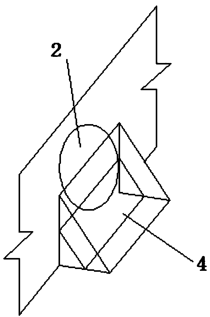
[0047] Embodiment two: if Figure 4 As shown, the shield machine passes through the upper part of the culvert 1, and the shield machine passes through the two sides and the top surface of the culvert 1. The specific removal method of the two sides and the top surface of the culvert 1 is as follows:

[0048] Step 1. According to the drilling route of the shield machine, determine the specific position where the two sides and the top surface of the culvert 1 are crossed, that is, the position where the culvert body 2 is crossed;

[0049] Step 2, grouting to rock mass or soil mass (such as Figure 5 shown)

[0050] Grouting in the side rock mass or soil body: extending 1 to 3 meters from the side crossed by the culvert body 2 to the surrounding, grouting in the rock mass outside the extension range and the rock mass outside the crossed culvert body 2;

[0051] Grouting in the rock mass or soil at the top: extending 1~3m from the top through the culvert 2 to the surrounding, gro...

Embodiment 3

[0057] Embodiment three: as Figure 7 As shown, the shield machine passes through the lower part of the culvert 1, and the specific removal method of the culvert body that is crossed on the two sides and the bottom of the culvert 1 is as follows:

[0058] Step 1. According to the drilling route of the shield machine, determine the specific position where the two sides and the bottom of the culvert 1 are crossed (that is, the specific position where the culvert body 2 is crossed);

[0059] Step 2. Grouting to rock mass or soil mass

[0060] Grouting in the side rock mass or soil body: extend 1-3 meters from the side crossed culvert to the surrounding, and grout in the rock mass outside the extension range and the rock mass outside the crossed culvert;

[0061] Step 3: Dismantle the crossed culvert by area and make support structure 4

[0062] (1) Demolition of the side of the culvert being crossed by the culvert: the removal method is the same as Step 3 of Embodiment 1;

[0...


PUM


Abstract

The invention discloses a non-open excavation dismantling construction method for drilled underground structure. The non-open excavation dismantling construction method comprises the following steps that firstly, the part of the underground structure being drilled and penetrated through is determined; secondly, grouting is conducted on a rock body or a soil body: thirdly, the part of the underground structure being penetrated through is subregionally dismantled, and a supporting structure is made; and fourthly, the part of the underground structure being penetrated through extends to the two ends, a safe distance is reserved, and formworks are closed for concrete grouting in the underground structure outside the safe distance, and the penetrating-through section of the underground structure is closed. The non-open excavation dismantling construction method for the drilled underground structure has the beneficial effects that compared with the current mode of open excavation, ground surface enclosure is reduced, trouble on the traffic does not occur, and non-open excavation construction does not produce noise, dust and the like; safe and reliable effects are achieved, before the structure is dismantled, grouting is conducted on the rock body or the soil body, and self-stability of the rock body and the soil body is ensured; the support structure are made in time when part of thestructure is dismantled, the safety of construction personnel is ensured; and concrete is backfilled for protection after dismantling, and the underground structure body is effectively prevented fromcollapse.

Description

technical field [0001] The invention relates to the technical field of underground construction, in particular to a non-excavation demolition construction method for an underground structure drilled by a shield machine or a pipe jacking machine. Background technique [0002] With the rapid development of society, the demand for urban transportation and environmental improvement is becoming more and more urgent, and the number of underground projects such as subways, comprehensive pipe corridors, and renovation and upgrading of rainwater and sewage pipes has surged. Underground projects mostly use shield machines and pipe jacking machines. Due to the lag of urban planning in China, shield machines and pipe jacking machines will inevitably encounter structures such as culverts, prefabricated concrete pipes, and steel pipes during the construction process. Due to the limitations of structure and pipe jacking construction, the original structure needs to be removed and rerouted....

Claims


Application Information

Patent Timeline
Patent Type & Authority Applications(China)
IPC IPC(8): E04G23/08
CPCE04G23/08
Inventor 高波
Owner NO 1 CONSTR ENG CO LTD OF CHINA CONSTR THIRD ENG BUREAU CO LTD
Features
  • R&D
  • Intellectual Property
  • Life Sciences
  • Materials
  • Tech Scout
  • Unparalleled Data Quality
  • Higher Quality Content
  • 60% Fewer Hallucinations
Learn More