Method for constructing concrete structure of subway contact passage through ground pouring and freezing method

A concrete structure and communication channel technology, which is applied in the fields of earthwork drilling, soil protection, and foundation structure engineering, can solve problems such as hidden dangers in structural quality, difficult quality control, poor continuity, etc., to reduce uneven settlement and shorten pouring time , The effect of saving pouring time

Active Publication Date: 2018-02-27
BEIJING CHINA COAL MINE ENG CO LTD
View PDF4 Cites 9 Cited by
  • Summary
  • Abstract
  • Description
  • Claims
  • Application Information

AI Technical Summary

Problems solved by technology

During the construction process, more than 90 square meters of concrete need to be poured manually, especially at the vault of the passage, it is difficult to pour the concrete densely, and it is easy to form cavities, resulting in the thickness of the structure not meeting the design requirements, causing hidden dangers to the quality of the structure
[0005] During the pouring process of the entire communication channel, the continuity is poor, the efficiency is low, and the average pouring time is as long as more than ten hours. Sometimes the time for pouring the concrete is too long, resulting in the initial setting of the concrete, which has to be discarded, and the waste is serious.
Because the quality is difficult to control during manual pouring, channel leakage often occurs

Method used


Image

  • Method for constructing concrete structure of subway contact passage through ground pouring and freezing method
  • Method for constructing concrete structure of subway contact passage through ground pouring and freezing method

Examples


Embodiment Construction

[0039] In order to clearly illustrate the solutions in the present invention, preferred embodiments are given below and detailed descriptions are given in conjunction with the accompanying drawings.

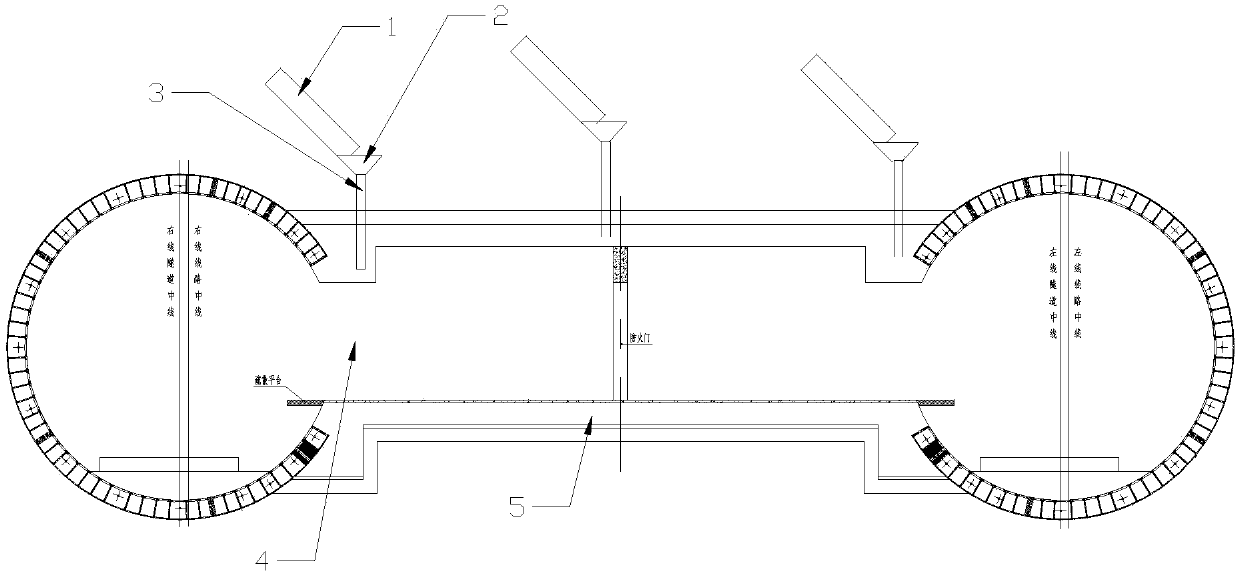
[0040] The method for constructing the concrete structure of the subway communication channel by ground pouring freezing method comprises the following steps:

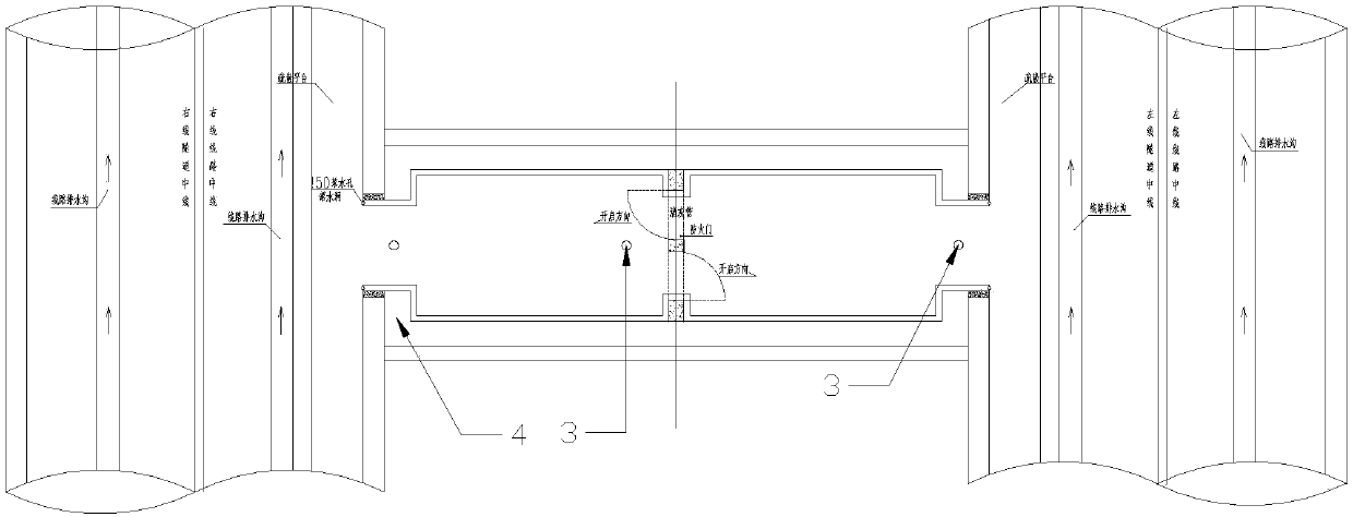
[0041] (1) Before the construction of the frozen hole in the communication channel, use a drilling rig to drill a hole in the center of the ground communication channel and at the 4 positions of the bell mouth on both sides. Inside, the bottom of the borehole located at the center of the communication channel is located above the bottom plate 5 of the communication channel. Wherein, the diameter of the drilled hole is larger than 159mm.

[0042] Before drilling from the ground above where the communication channel is located to where the communication channel is located, it is necessary to perform ground measurement and ...


PUM


Abstract

The invention discloses a method for constructing a concrete structure of a subway contact passage through a ground pouring and freezing method. The method for constructing the concrete structure of the subway contact passage comprises the following steps that (1) drilling is conducted from the ground above the contact passage toward the interior of the contact passage; (2) concrete sliding tubesare placed downwards in drilled drill holes in the step (1); (3) after a frozen wall meets the excavation condition of the contact passage, earth excavation of the contact passage is conducted in a subway tunnel, and protective treatment is conducted on the concrete sliding tubes after the concrete sliding tubes are dug out; and (4) the concrete structure of a bottom plate (5) of the contact passage is poured by utilizing the concrete sliding tube located in the center of the contact passage, and the side wall concrete structure and the arch crown concrete structure concrete structure are poured by utilizing the concrete sliding tubes located in the flare opening position. According to the method for constructing the concrete structure of the subway contact passage through the ground pouring and freezing method, compact pouring of concrete on an arch crown of the contact passage can be achieved, opening or holes in the concrete on the arch crown of the contact passage can be effectively prevented, it is effectively ensured that the thickness of the concrete structure of the contact passage meets the design requirement, and hidden dangers caused by the quality of the concrete structure of the contact passage are eliminated.

Description

technical field [0001] The invention relates to the field of subway construction, in particular to a method for constructing a concrete structure of a subway communication channel by a ground pouring and freezing method. Background technique [0002] The connecting channel is generally designed as a straight wall + semi-circular arch section, and the construction scheme of "horizontal freezing in the tunnel to reinforce the soil, and underground excavation in the tunnel" is often used for construction, that is, the horizontal freezing method is used in the tunnel to strengthen the ground. Freeze the surrounding soil of the communication channel to form a high-strength and well-closed frozen soil curtain, and then use the underground excavation method to excavate and construct the channel and pumping station under the protection of the frozen soil curtain. [0003] At present, subway tunnels are mainly constructed using the shield method, but the underground chambers such as ...

Claims


Application Information

Patent Timeline
Patent Type & Authority Applications(China)
IPC IPC(8): E21D11/10E21D11/38E02D3/115
CPCE21D9/001E21D11/10E21D11/38
Inventor 赵玉明崔灏郭垒李宁许舒荣高伟王恒孙右好李志军刘伟民
Owner BEIJING CHINA COAL MINE ENG CO LTD
Why Eureka
Try Eureka