
Internally-installed ring-type permanent magnet magnetic bearing and machining method thereof

A magnetic bearing and permanent magnet technology, applied in the field of bearings, can solve problems such as noise, bearing wear, and heat generation, and achieve the effects of simple material selection, long service life, and elimination of mechanical friction

Inactive Publication Date: 2018-02-27
NANCHANG INST OF TECH
View PDF9 Cites 0 Cited by
  • Summary
  • Abstract
  • Description
  • Claims
  • Application Information

AI Technical Summary

Problems solved by technology

[0003] The invention provides a permanent magnet magnetic bearing in the form of a built-in ring and a processing method thereof. The bearing device uses permanent magnets to repel each other with the same sex, which can eliminate mechanical friction, reduce wear, energy consumption and noise, and has long service life without lubrication, thereby solving the existing problems. Bearings have problems such as wear, noise, and heat

Method used


Image

  • Internally-installed ring-type permanent magnet magnetic bearing and machining method thereof
  • Internally-installed ring-type permanent magnet magnetic bearing and machining method thereof
  • Internally-installed ring-type permanent magnet magnetic bearing and machining method thereof

Examples


Embodiment Construction

[0023] A specific embodiment of the present invention will be described in detail below with reference to the accompanying drawings, but it should be understood that the protection scope of the present invention is not limited by the specific embodiment.

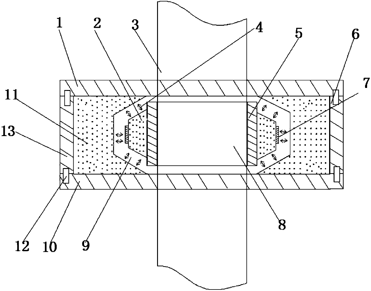
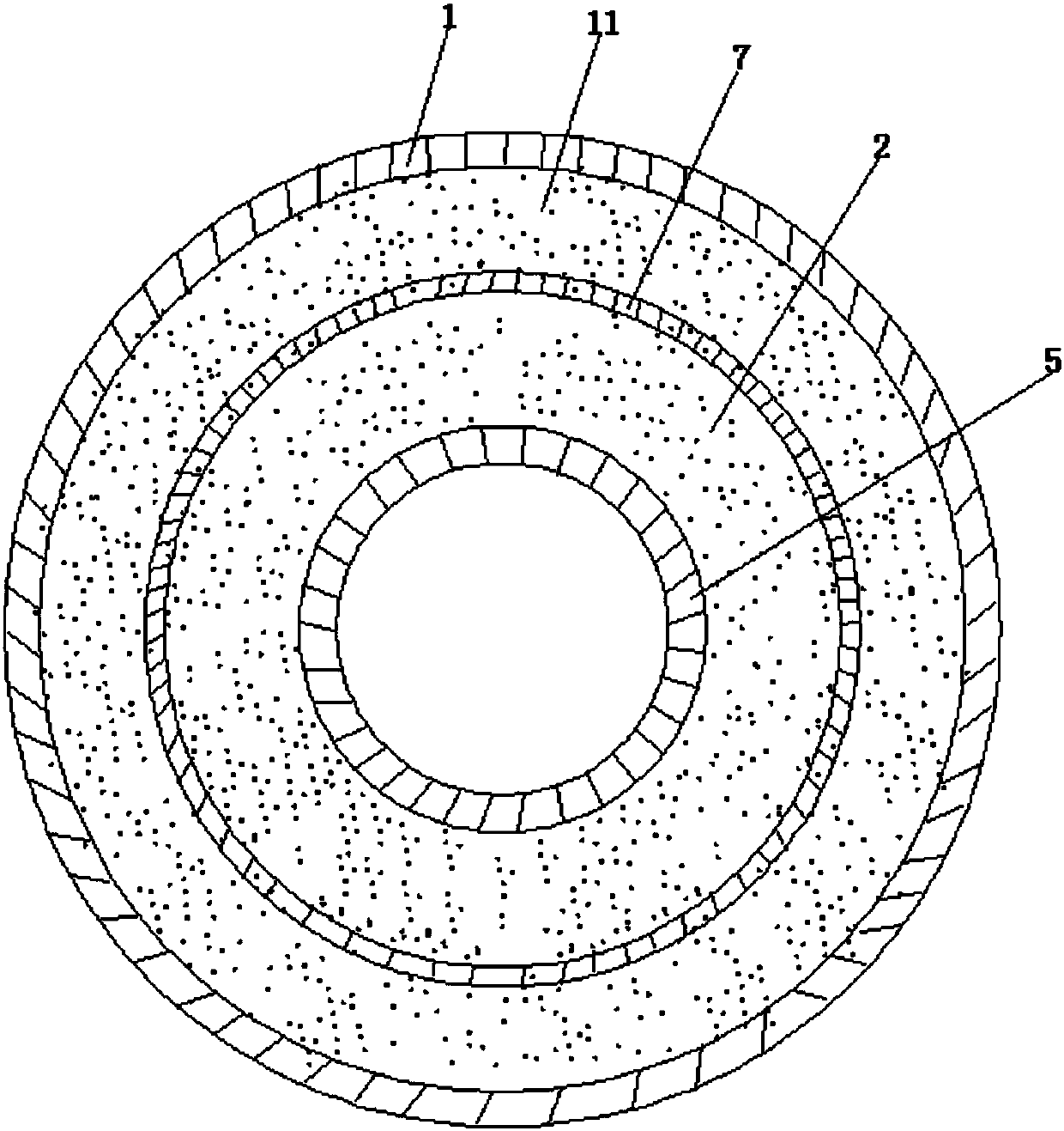
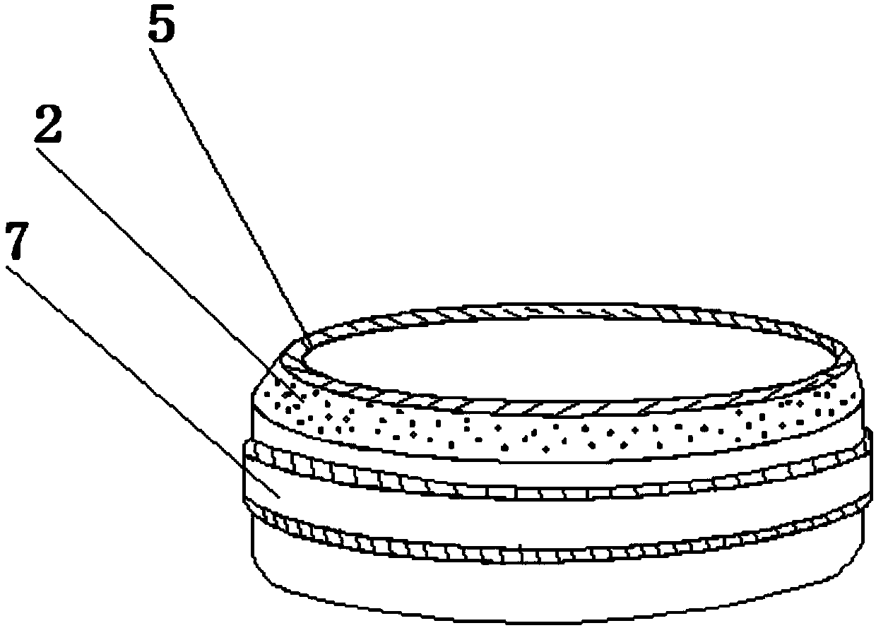
[0024] like Figure 1 to Figure 7 As shown, the built-in ring form permanent magnet magnetic bearing provided by the embodiment of the present invention includes a rotor and a stator; the stator includes an annular stator magnet 11, a stator outer casing 13, a stator upper cover 1 and a stator lower cover 10; the rotor includes The rotor magnet 2 , the rotating shaft sleeve 5 and the rotor magnet outer sleeve 7 ; the stator magnet 11 is annular and has a slot 9 inside it; the outer fixed sleeve of the stator magnet 11 has an annular stator outer sleeve 13 ; A ring-shaped rotor magnet 2 with the same shape is placed; the inner fixed sleeve of the rotor magnet 2 is provided with an annular rotating shaft sleeve 5, and the rota...


PUM


Abstract

The invention discloses an internally-installed ring-type permanent magnet magnetic bearing and a machining method thereof. The internally-installed ring-type permanent magnet magnetic bearing comprises a rotor and a stator. The stator comprises an annular stator magnet, a stator outer sleeve, a stator upper cover and a stator lower cover. The rotor comprises a rotor magnet, a rotating shaft sleeve and a rotor magnet outer sleeve. The stator magnet is annular, and the interior of the stator magnet is provided with a clamping groove. The exterior of the stator magnet is fixedly provided with the annular stator outer sleeve in a sleeved mode. The interior of the clamping groove is provided with the annular rotor magnet, wherein the shape of the rotor magnet is the same as the clamping groove. The interior of the rotor magnet is fixedly provided with the annular rotating shaft sleeve in a sleeved mode. The rotating shaft sleeve is internally provided with a rotating shaft. The periphery of the middle of the exterior of the rotor magnet is fixedly provided with the rotor magnet outer sleeve in a sleeved mode. The internally-installed ring-type permanent magnet magnetic bearing utilizesthe fact that the same permanent magnets are repelled with each other, mechanical friction can be eliminated, abrasion, energy consumption and noise are reduced, lubrication is not required, and theservice life is long, so that the problems such as abrasion, noise and heating of an existing bearing are solved, the mechanical production efficiency is improved, and the production cost is reduced.

Description

technical field [0001] The invention relates to the field of bearings, in particular to a permanent magnet magnetic bearing in the form of a built-in ring and a processing method thereof. Background technique [0002] At present, bearings commonly used in the machinery industry include rolling bearings, sliding bearings, joint bearings, etc. Under the action of periodic loads, the bearing surface is prone to fatigue damage, that is, cracks and spalling occur, which is an important damage situation for bearings; in addition, bearings During operation, not only rolling friction but also sliding friction occurs between the ferrule, rolling element and cage, which causes the bearing parts to wear; due to the mechanical contact between the relatively moving parts, wear, Noise, heat and other problems, thus reducing the production efficiency of the machine; and in order to make the bearing fully play and maintain its due performance for a long time, the bearing needs to be maintai...

Claims


Application Information

Patent Timeline
IPC IPC(8): F16C32/04F16C43/00
CPCF16C32/0408F16C43/00
Inventor 胡瑞许春霞何翠群朱春生谭德坤闫肖肖朱仁淼陶珍代芳温林成
Owner NANCHANG INST OF TECH
Learn More