Laser triggered multistage vacuum switch

A vacuum switch and laser technology, applied in electronic switches, spark gaps with auxiliary triggering devices, electrical components, etc., can solve problems such as limiting the application voltage level of laser-triggered vacuum switches, and avoid complex processes and high costs. The effect of large active area and improved conduction performance

Active Publication Date: 2018-02-27
DALIAN UNIV OF TECH
View PDF4 Cites 7 Cited by
  • Summary
  • Abstract
  • Description
  • Claims
  • Application Information

AI Technical Summary

Problems solved by technology

This is due to the non-linear growth relationship between the withstand voltage level of the vacuum gap and its gap distance, which limits the application voltage level of the laser trigger vacuum switch

Method used


Image

  • Laser triggered multistage vacuum switch
  • Laser triggered multistage vacuum switch
  • Laser triggered multistage vacuum switch

Examples


Embodiment Construction

[0034] The specific embodiments of the present invention will be described in detail below in conjunction with the technical solutions and accompanying drawings.

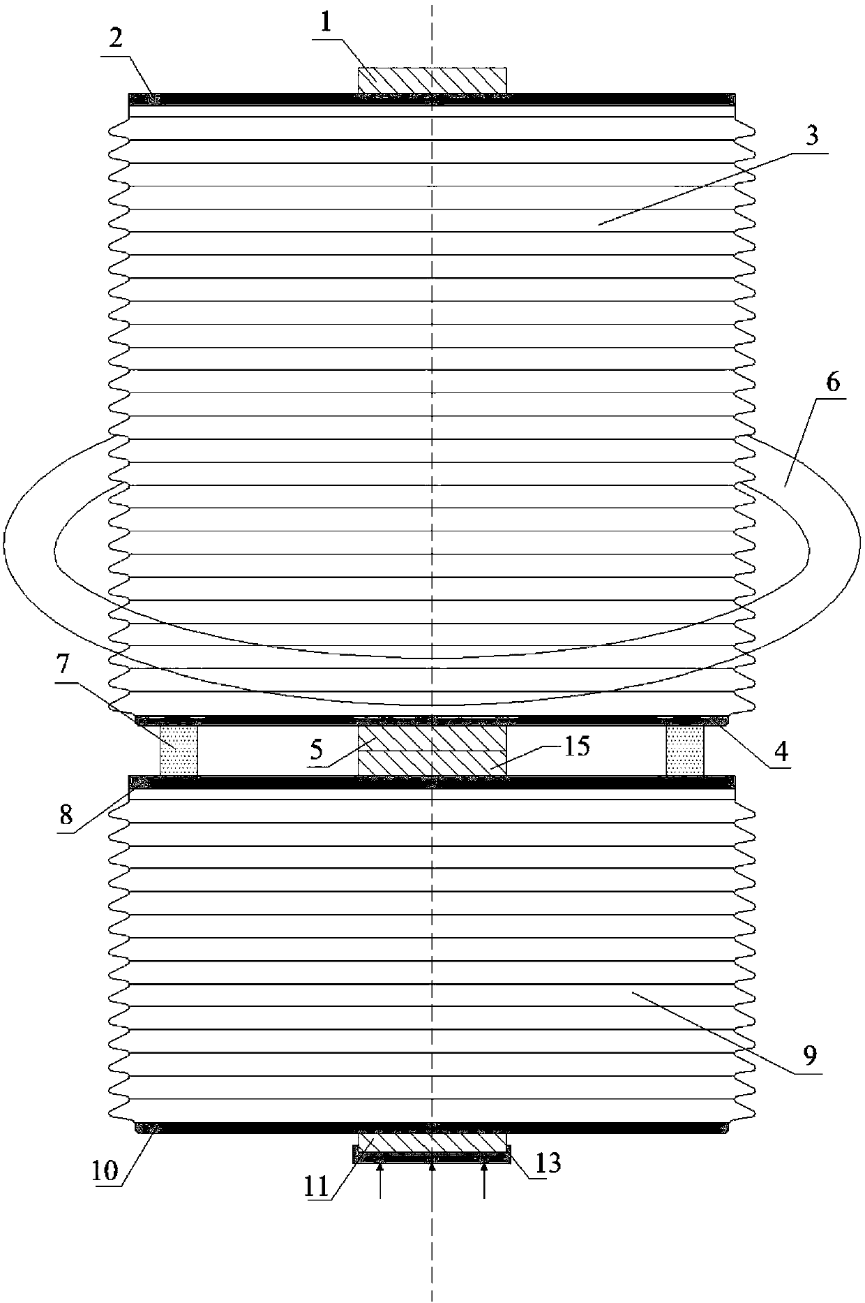
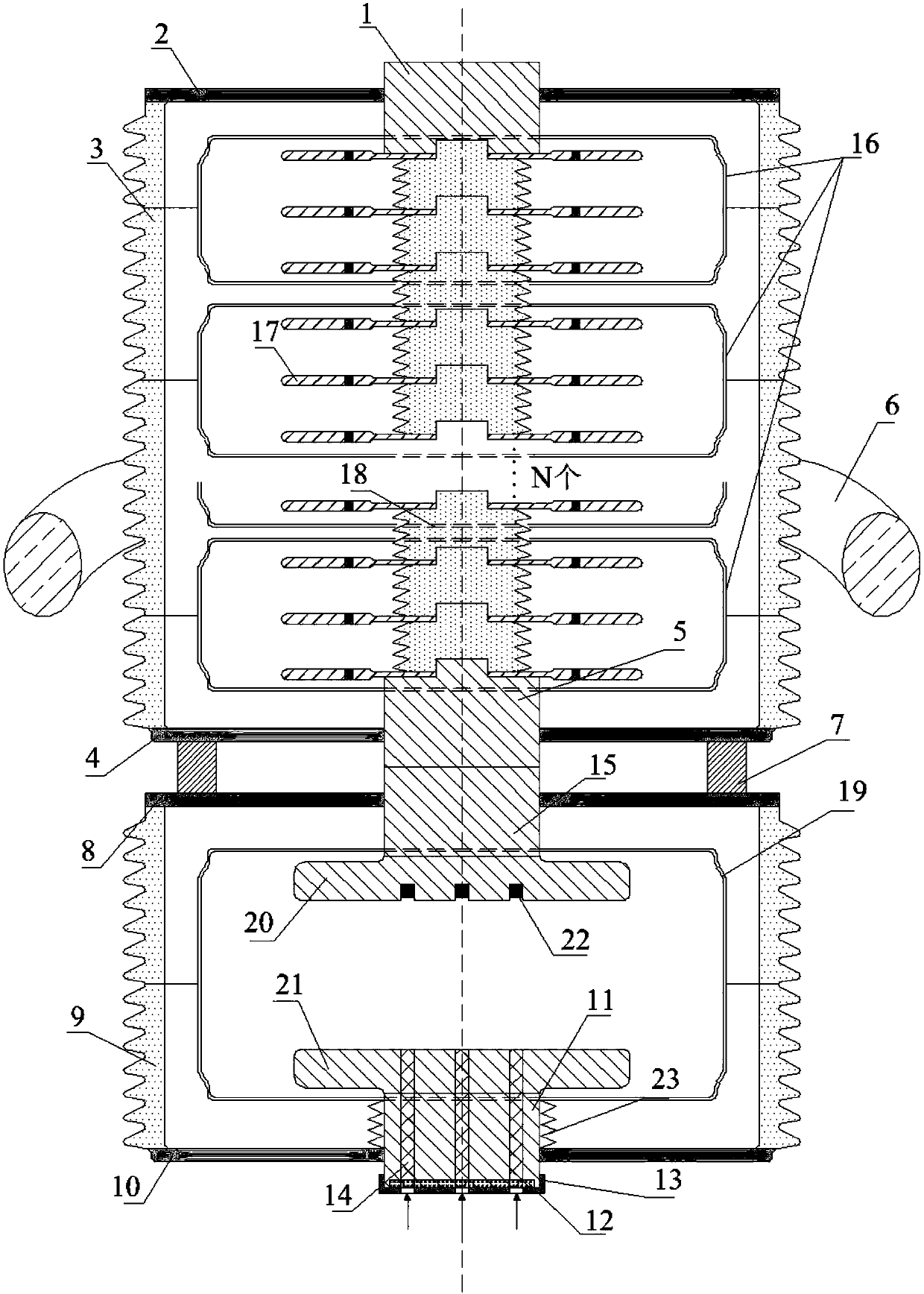
[0035] combine Figure 1 to Figure 6 , a laser-triggered multi-stage vacuum switch, comprising a laser-triggered vacuum gap, a multi-stage self-breakdown vacuum gap and a trigger system;

[0036] The multi-stage self-breakdown vacuum gap is fixed on the upper end of the laser-triggered vacuum gap through the fastening connector 7, and the pressure equalizing ring 6 is set outside the upper insulating shell 3;

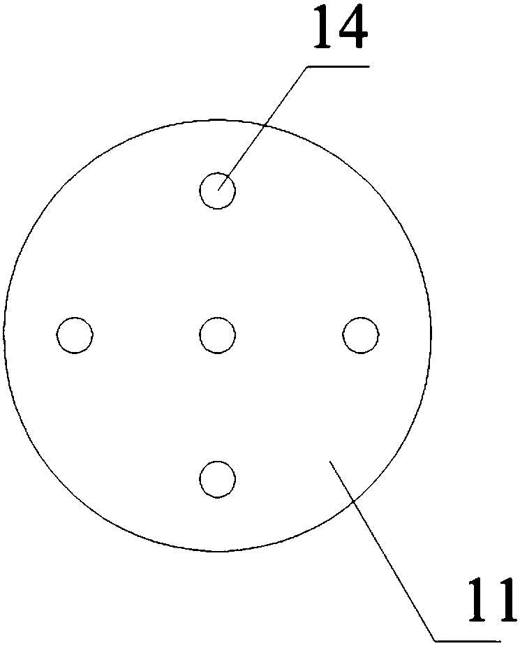
[0037] The laser trigger vacuum gap includes a lower insulating shell 9, a trigger upper end cover flange 8, a trigger gap shield 19, a trigger lower end cover flange 10, a cathode conductive rod 15, and a flat cathode contact 20 with multiple target electrodes. , Trigger target 22, flat anode contact 21 with multiple light holes, anode conductive rod 11 with multiple light holes, bellows 23, light lens 12 a...


PUM


Abstract

The invention belongs to the technical field of high voltage and high power pulse power switch, in particular to a laser triggered multistage vacuum switch. The laser triggered multistage vacuum switch comprises a laser triggered vacuum clearance, a multistage self-breakdown vacuum clearance and a trigger system; the multistage self-breakdown vacuum clearance is fixed to the upper end of the lasertriggered vacuum clearance through the fastening connecting parts; and a pressure equalizing ring is covered outside the upper insulating shell. According to the invention, the series technique of the laser triggered vacuum clearance and the multistage self-breakdown vacuum clearance is adopted, and the laser triggered vacuum clearance and the multistage self-breakdown vacuum clearance are coordinated each other to achieve the application of the laser triggered multistage vacuum switch in a high voltage, high repetition frequency and high power pulse power system; and multiple channels of laser are used to bombard the trigger target material simultaneously, therefore, the affect area of the laser on the target material is increased, more initial plasmas are generated, and the conduction performance of the laser triggered vacuum switch is further improved. Using the laser triggered multistage vacuum switch, the complex process and high cost required by long term maintenance is avoided.

Description

technical field [0001] The invention belongs to the technical field of high-voltage and high-power pulse power switches, and in particular relates to a laser-triggered multi-stage vacuum switch. Background technique [0002] With the continuous progress of my country's high-power, high-repetition-frequency pulse power technology research and the continuous growth of the capacity of the pulse power system, the pulse power system's conduction delay, current capacity, high-frequency breaking, and service life of the switching device Key operating characteristics put forward higher requirements. At present, there are two types of pulse power switching devices widely used: gas trigger switch and vacuum trigger switch; according to the switch trigger mode, it can be divided into two types: electric pulse trigger and laser trigger. Among them, the electric pulse trigger switch is to set a trigger electrode in the gap between the main electrodes, and use high-voltage pulse discharge...

Claims


Application Information

Patent Timeline
Patent Type & Authority Applications(China)
IPC IPC(8): H03K17/54
CPCH03K17/54H03K2217/941H01T2/00H01T4/12H01T4/20
Inventor 廖敏夫陈占清段雄英黄智慧张豪刘旭
Owner DALIAN UNIV OF TECH
Why Eureka
Try Eureka