Side bearing and preparation method thereof

A side bearing box and metal plate technology, which is applied in the direction of the device that moves relative to each other laterally between the underframe and the bogie, can solve the problems of stress concentration on the bonding surface between metal and rubber, large stiffness variation with temperature, side bearing Unstable friction torque and other problems, to achieve the effect of suppressing snaking motion, solving frictional resistance torque and large wear, and reducing operating costs

Active Publication Date: 2018-03-02
JIANGSU UNIV OF SCI & TECH
View PDF9 Cites 0 Cited by
  • Summary
  • Abstract
  • Description
  • Claims
  • Application Information

AI Technical Summary

Problems solved by technology

[0003] Purpose of the invention: The purpose of the present invention is to provide a side bearing to solve the problems of unstable friction torque, cracks in elastic elements, large and unstable stiffness with temperature, large permanent deformation, and metal and rubber bonding commonly found in existing side bearings. The surface is prone to stress concentration, fatigue damage, short service life, high maintenance cost, and is not conducive to environmental protection.
[0004] Another object of the present invention is to provide a preparation method of side bearings, which solves the problems of low strength, poor stability, complicated installation and difficult disassembly of existing side bearings

Method used


Image

  • Side bearing and preparation method thereof
  • Side bearing and preparation method thereof
  • Side bearing and preparation method thereof

Examples


Embodiment Construction

[0025] The present invention will be further described below in conjunction with accompanying drawing.

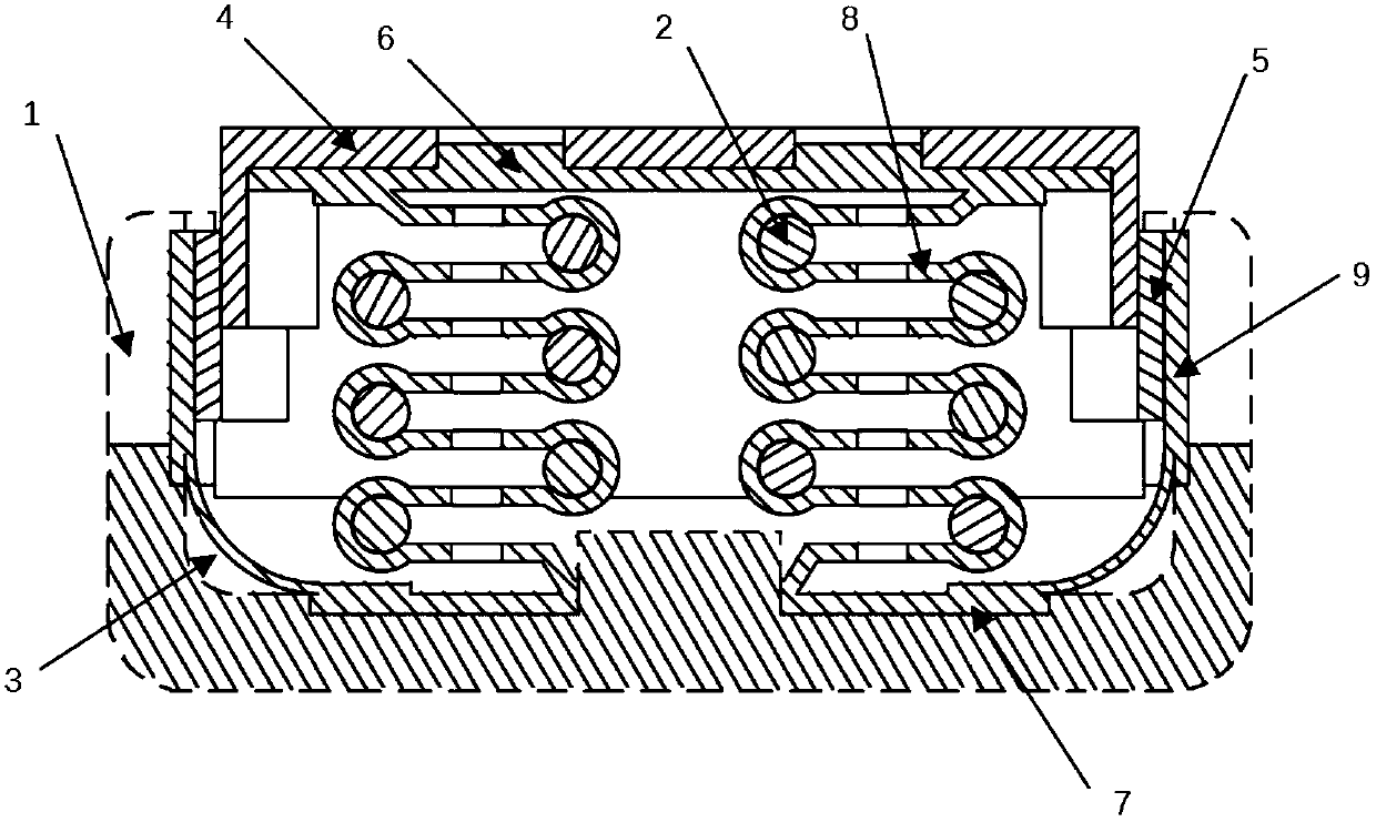
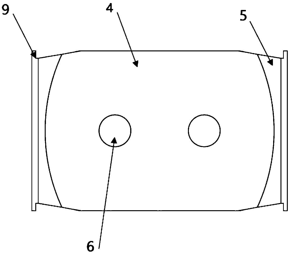
[0026] Such as Figure 1-2 As shown, the elastic side bearing includes a side bearing box 1, and the side bearing box 1 is equipped with a side bearing packaging frame 3 and a side bearing elastic assembly. The side bearing packaging frame includes a base 7, a main body upper plate 6 and a main body side ear 9. The side bearing elastic The component is assembled between the base 7 and the main body upper plate 6, and the side bearing elastic component includes two multi-layer S-shaped metal plates 8, the materials and layers of the two S-shaped metal plates 8 are the same, and the two S-shaped metal plates 8 are arranged anti-symmetrically. The two metal plates 8 are positioned by the bosses provided on the base 7. The transition arc of the first layer of each S-shaped metal plate is located away from the bosses. This arrangement can effectively save space. The number of ...


PUM

PropertyMeasurementUnit
elastic modulusaaaaaaaaaa
thicknessaaaaaaaaaa
elastic modulusaaaaaaaaaa

Abstract

The present invention discloses a side bearing. The side bearing comprises a side bearing box. A side bearing packaging frame and an elastic component are assembled in the side bearing box. The side bearing packaging frame comprises a pedestal, a main body upper plate and main body side lugs. The elastic component is assembled between the pedestal and the main body upper plate. The main body upperplate is provided with an upper wearing plate, and two ends of the upper wearing plate are provided with downward extending ends. A side wearing block is disposed between one main body side lug and the corresponding upper wearing plate extending end, and the upper wearing plate extending end is tightly attached to the corresponding side wearing block with an arc-shaped curved surface. The elasticcomponent comprises at least one multilayer S-shaped metal plate, arc transition is carried out for corners of the metal plate, a hollow groove is enclosed by the arc, and a supporting roller is assembled in each hollow groove. The side bearing is simple and convenient to disassemble and assemble, later maintenance is easy, the elastic component of the side bearing has high bearing capability, rigidity adjusting range is wide, stress is uniform, permanent deformation is little, the application range of the side bearing is enlarged, lifetime of the side bearing is prolonged, stability of the side bearing is improved, the stress concentration phenomenon is effectively prevented, a stable frictional resistance torque is provided, and vehicle operation safety is improved.

Description

technical field [0001] The invention relates to railway transport vehicle accessories, in particular to an elastic side bearing. Background technique [0002] The main function of the side bearing is to slow down the snaking motion of the vehicle and ensure the appropriate turning resistance moment between the bogie and the car body. The side bearing is one of the key components to ensure the stability and safety of the railway vehicle. At present, the existing side bearings in my country include gap type elastic side bearings and constant contact elastic side bearings. Gap-type elastic side bearings, that is, when the vehicle is running in a straight line, usually the upper and lower side bearings do not touch, but there is a certain gap. Therefore, the disadvantage of the gap side bearing is that when a small side roll occurs, the vehicle body cannot be restrained by the frictional resistance moment, the critical speed is low, and the running stability is poor. The exist...

Claims


Application Information

Patent Timeline
Patent Type & Authority Applications(China)
IPC IPC(8): B61F5/14B23P13/02
CPCB61F5/14B23P13/02
Inventor 沈超明汪雅棋杨绘峰周俊俊
Owner JIANGSU UNIV OF SCI & TECH
Why Eureka
Try Eureka