Vision guiding tunnel sign point coordinate laser measurement system and method

A laser measurement system and vision-guided technology, applied in measuring devices, surveying and navigation, and optical devices, to achieve fast measurement, simple structure, and flexible application

Inactive Publication Date: 2018-03-02
ZHEJIANG UNIV
View PDF14 Cites 13 Cited by
  • Summary
  • Abstract
  • Description
  • Claims
  • Application Information

AI Technical Summary

Problems solved by technology

[0005] The present invention overcomes the deficiencies of some existing tunnel profile monitoring methods,

Method used


Image

  • Vision guiding tunnel sign point coordinate laser measurement system and method
  • Vision guiding tunnel sign point coordinate laser measurement system and method

Examples


Embodiment Construction

[0026] The present invention will be further described below in conjunction with drawings and embodiments.

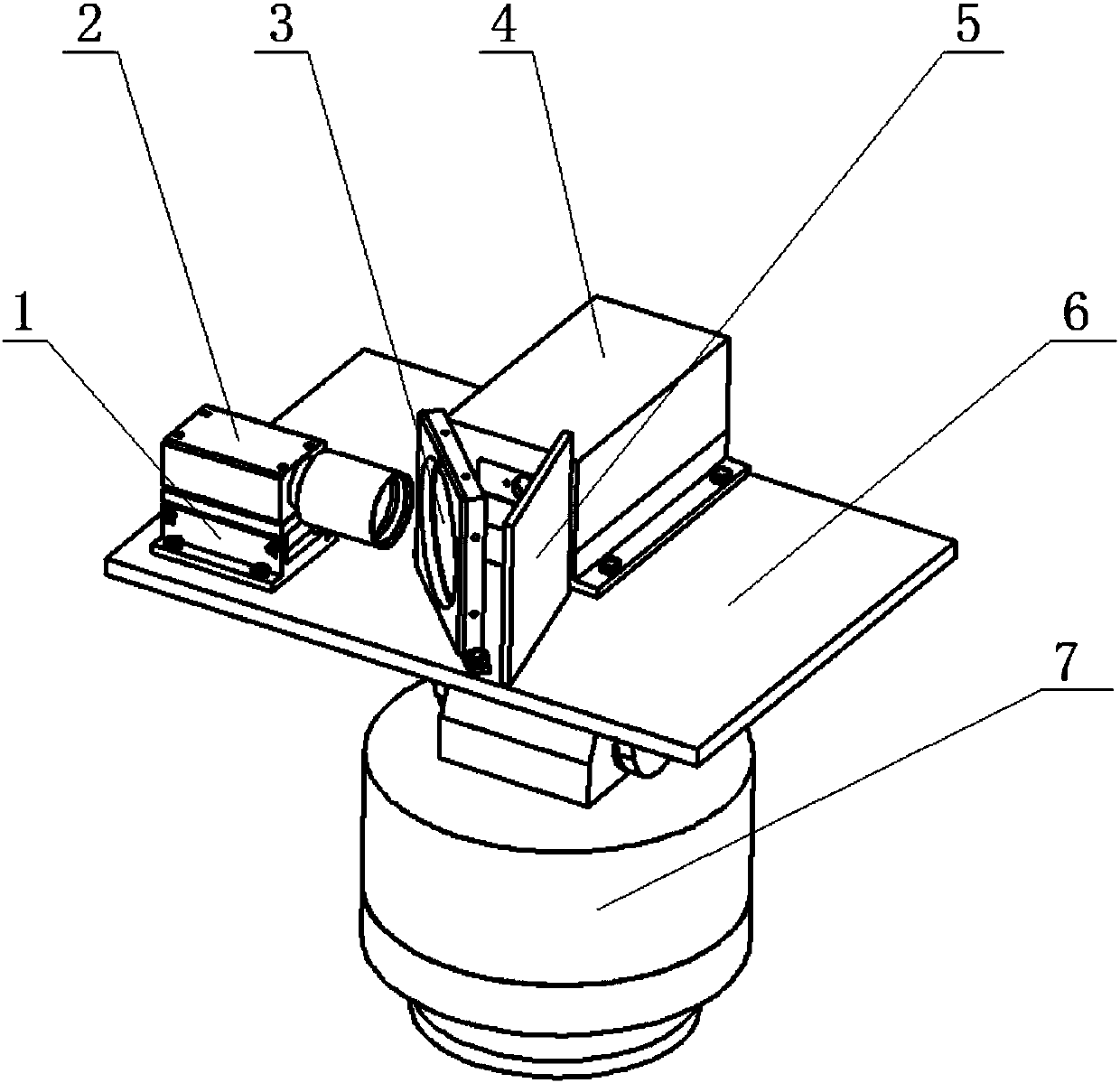
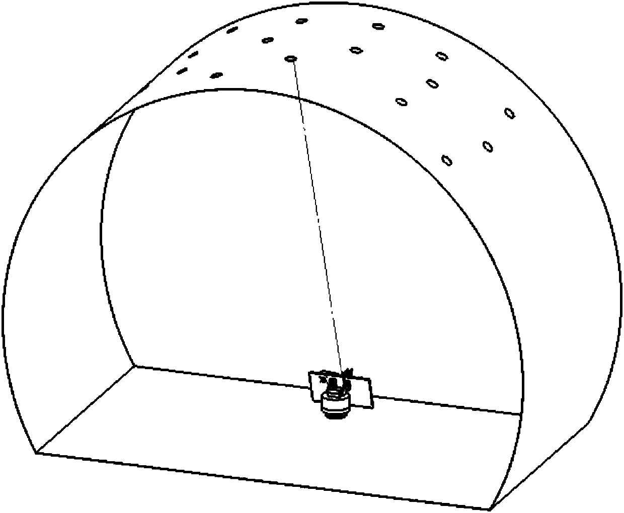
[0027] The specific implementation of the invention includes marking points arranged on the rock wall of the tunnel, a visible light lamp irradiated on the rock wall of the tunnel and a coordinate measuring device for the marking points. Such as figure 1 As shown, the marker point coordinate measuring device includes a camera mounting table 1 for adjusting the pose of the industrial camera, an industrial camera 2 for assisting laser aiming, a narrow-band filter 3 for reflecting visible light through the laser, and a The laser displacement sensor 4 for the distance from the point to the measuring device, the shading plate 5 for absorbing part of the laser light and blocking the ambient light, the mounting plate 6 for connecting the pan / tilt and other components, and driving the measuring device for horizontal rotation and vertical pitch Sports gimbal 7;

[0028] The mo...


PUM


Abstract

The invention discloses a vision guiding tunnel sign point coordinate laser measurement system and method. The system comprises a sign point arranged on a tunnel rock wall, a visible light lamp capable of irradiating onto the tunnel rock wall and a sign point coordinate measurement device, wherein for the sign point coordinate measurement device, a mounting plate is mounted on a top end of a holder capable of doing horizontal rotation and vertical pitching movement, an industrial camera and a laser displacement sensor are fixed on the mounting plate, the probe axis direction of the industrialcamera is perpendicular to the laser emission direction of the laser displacement sensor, a narrowband filter is further fixedly arranged at a crossing portion of the probe axis of the industrial camera and the laser emission line of the laser displacement sensor, the narrowband filter is fixed on the mounting plate, and a shadow shield is arranged at one side of the narrowband filter far from theindustrial camera. The device is advantaged in that the structure is simple, application is flexible, tunnel sign point coordinate measurement can be automatically accomplished, and automatic non-contact tunnel contour monitoring is realized.

Description

technical field [0001] The invention relates to the technical field of automatic laser measurement, in particular to a vision-guided laser measurement system and method for the coordinates of tunnel marking points. Background technique [0002] With the progress and development of modern society, the demand for tunnel construction is increasing. During the tunnel construction process, the cave body is deformed by the force of the surrounding rock mass. The deformation of the tunnel is the main factor affecting the construction safety. Excessive tunnel deformation will cause accidents such as tunnel collapse, casualties, and equipment damage. Early warning when the deformation is large will reduce losses and even prevent accidents. Therefore, it is particularly important to monitor the deformation of the tunnel profile. At present, the tunnel profile monitoring methods are mainly divided into contact measurement and non-contact measurement. [0003] Contact measurement main...

Claims


Application Information

Patent Timeline
IPC IPC(8): G01B11/24G01B11/16G01C7/06
CPCG01B11/24G01B11/16G01C7/06
Inventor 李华雷勇甘创赵斌
Owner ZHEJIANG UNIV
Why Eureka
Try Eureka