Reading head optimization distribution method for angle encoder self calibration

A technology of an angle encoder and an arrangement method, which is applied to instruments, measuring devices, etc., can solve the problems of a large number of reading heads, increased costs, complicated algorithms and difficult to operate, etc., and achieves the effect of in-situ calibration and low cost.

Active Publication Date: 2018-03-02
SHANGHAI MICRO H MOTION AUTOMATION
View PDF10 Cites 15 Cited by
  • Summary
  • Abstract
  • Description
  • Claims
  • Application Information

AI Technical Summary

Problems solved by technology

After searching the existing technical literature, it is found that the US patent No. US7840372B2 uses the TDR method to calibrate the angle encoder, but this method can only be used to calibrate the spindle with negligible friction resistance such as air bearing or magnetic bearing, and its algorithm is complicated Difficult to operate; the U.S. Patent No. US7143518B2 adopts the method that M reading heads are evenly distributed at equal angular intervals around the circular grating, and can calibrate all remaining harmonic components except for M and multiples of M in the angular error, but for To obtain high calibration accuracy, generally more than five reading heads are required. This method not only has the problem of difficult installation and adjustment of the reading heads, but also increases the corresponding cost.
There are also other literatures that give a number of reading head layout schemes for self-calibration of angle encoders, but there are problems such as using a large number of reading heads, and the layout method has not been optimized.

Method used


Image

  • Reading head optimization distribution method for angle encoder self calibration
  • Reading head optimization distribution method for angle encoder self calibration
  • Reading head optimization distribution method for angle encoder self calibration

Examples


Embodiment Construction

[0052] The preferred embodiments of the present invention are given below in conjunction with the accompanying drawings to describe the technical solution of the present invention in detail.

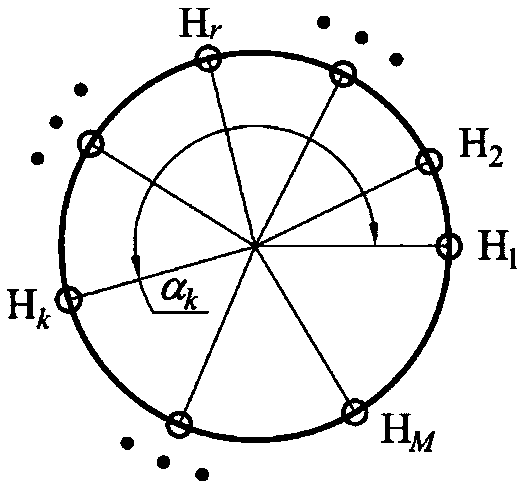
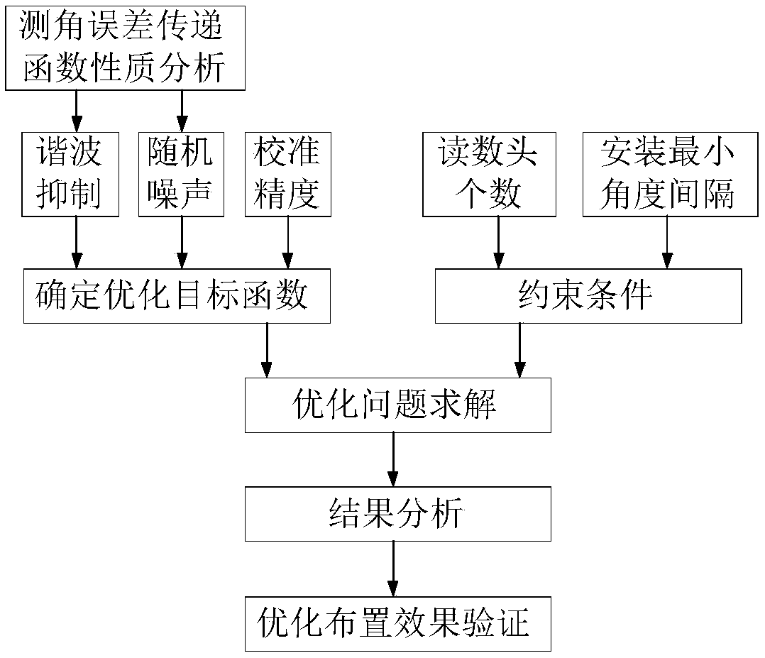
[0053] The method shown in the present invention is further described in detail according to the accompanying drawings. The angle encoder is equipped with M reading heads. The present invention solves how to arrange these M reading heads so that the difference between the calibration curve obtained and the real angular error curve of the encoder The relative error between them is the smallest, that is, the calibration accuracy is the highest. The method for optimizing the layout of the reading head for the self-calibration of the angle encoder of the present invention includes the following steps:

[0054] Step 1: Determine the transfer function in the angle measurement error analysis and analyze its characteristics

[0055] The kth reading head H k Relative to the first readhead H 1 T...


PUM


Abstract

The invention relates to a reading head optimization distribution method for angle encoder self calibration. The method comprises steps that a Fourier analytical method is employed to determine a transfer function of angle measurement error analysis and analyze characteristics; optimization targets are determined through comprehensively considering harmonic wave inhibition, random noise and calibration precision factors; initial parameters including the reading head number and the total calibration harmonic wave number and reading head mounting smallest angle interval constraint conditions aredetermined, and an optimization problem is solved. The method is advantaged in that high-precision, rapid, real-time and in-place calibration of an angle encoder can be realized, cost is lower, a two-reading head optimal distribution scheme is suitable for common high-precision test systems, and a three-reading head optimization system can be applied to super-high-precision calibration occasions.

Description

technical field [0001] The invention relates to a method for calibrating an angle measuring device in the field of precision measurement, in particular to a method for optimizing the layout of a reading head for self-calibrating an angle encoder. Background technique [0002] Angle encoders are key components in the field of precision measurement, and are mainly used in high-precision measurement devices for angle values, such as machine tool rotary tables, precision turntables, and national benchmarks for angle measurement. A typical angle encoder mainly includes a circular grating code disc and a reading head. In the actual working process, the measurement accuracy of the angle encoder is affected by many factors, including: the accuracy of the grating pitch, the quality of signal subdivision, the installation deformation of the grating, the installation and adjustment error of the reading head, and the installation of the grating relative to the bearing Eccentricity, bea...

Claims


Application Information

Patent Timeline
Patent Type & Authority Applications(China)
IPC IPC(8): G01B21/22
CPCG01B21/22
Inventor 刘品宽
Owner SHANGHAI MICRO H MOTION AUTOMATION
Why Eureka
Try Eureka