
Compensation structure and method for eliminating dynamic error of heavy rain and light rain

A dynamic error and compensation structure technology, applied in the direction of rainfall/precipitation gauges, measuring devices, meteorology, etc., can solve the problems of inaccurate measurement, poor precision, and small number of buckets, etc., and achieve improved measurement accuracy, simple structure, and easy setup reasonable effect

Pending Publication Date: 2018-03-02
福州小草科技有限公司
View PDF7 Cites 10 Cited by
  • Summary
  • Abstract
  • Description
  • Claims
  • Application Information

AI Technical Summary

Problems solved by technology

In the existing tipping bucket rain gauge, it is difficult to adjust the tilting angle of the tipping bucket in a linear ratio corresponding to the water quality in the tipping bucket, and the adjustment is difficult and the accuracy is poor
[0003] When the water drips into a bucket and reaches a critical equilibrium state, the tipping bucket will turn over. During the turning process, the rainwater will continue to flow down until the tipping bucket turns over the central axis. The water is not included in the theoretical measurement. We call it dynamic loss. , it is obvious that the loss of heavy rain will be much greater than that of light rain, which causes the number of buckets of heavy rain to be less than that of light rain, resulting in inaccurate measurement.

Method used


Image

  • Compensation structure and method for eliminating dynamic error of heavy rain and light rain
  • Compensation structure and method for eliminating dynamic error of heavy rain and light rain
  • Compensation structure and method for eliminating dynamic error of heavy rain and light rain

Examples


Embodiment Construction

[0024] The present invention will be further described below in conjunction with the accompanying drawings and specific embodiments.

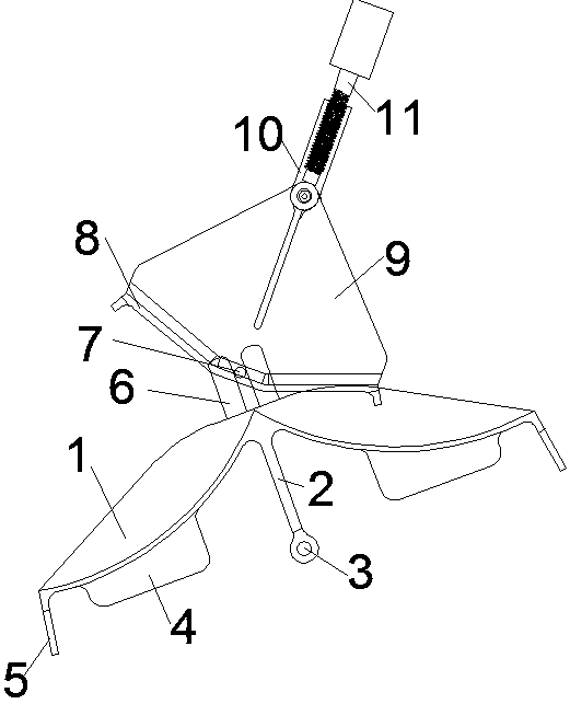
[0025] Such as figure 1 As shown, a compensation structure for eliminating the dynamic error of large and small rains includes a frame, an upper bucket, and a dump body located below the upper bucket. Two dump chambers are arranged symmetrically on the left and right sides of the dump body. Connected, the upper bucket and the tipping bucket body are turned over synchronously through a linkage, and the upper bucket and the tipping bucket body turn in opposite directions.

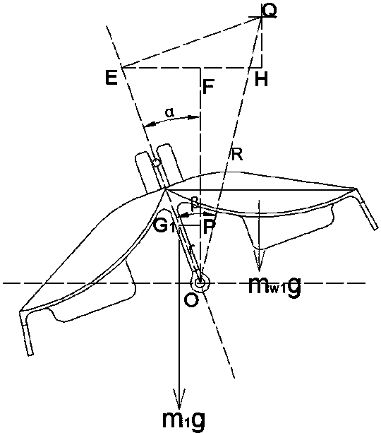
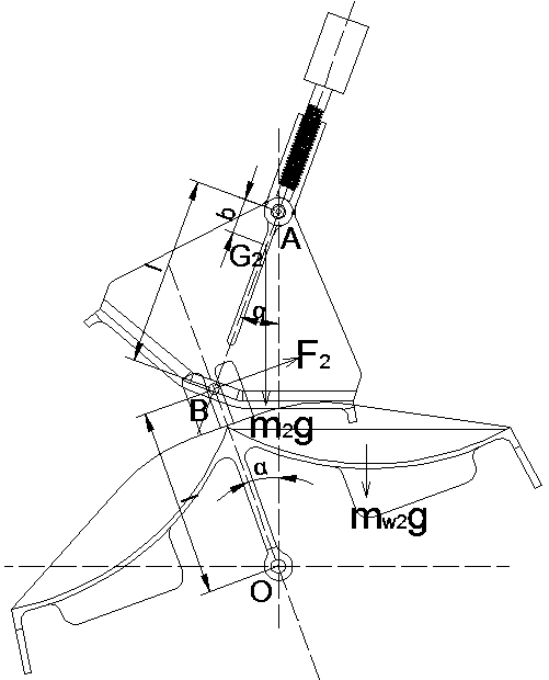
[0026] In this embodiment, the body of the dumping bucket is provided with a rotating shaft O, and the bottom surface of the dumping bucket chamber is a curved surface of rotation. It should be noted that the bottom surface of the bucket chamber is only a part of the curved surface of rotation. The part of the rotating body formed by the rotating shaft overlaps with the dumpi...


PUM


Abstract

The invention relates to a compensation structure and method for eliminating the dynamic error of heavy rain and light rain. The compensation structure comprises a frame, an upper bucket, and a dump bucket body. Two dump bucket rooms are arranged on the dump bucket body horizontally symmetrically. The upper bucket and the dump bucket body are in rotatable connection with the frame and are synchronously overturned by a linkage member in opposite directions. The upper middle part of the upper bucket is in rotatable connection with the frame via a rotating shaft A. The lower middle part of the dump bucket body is in rotatable connection with the frame through a rotating shaft O. The rotating shaft A and the rotating shaft O are parallel. The bottom surfaces of the dump bucket rooms are rotating curved surfaces. The rotation axis of the rotating curved surfaces is parallel to the rotating shaft O of the dump bucket body, and is located on the upper side of the dump bucket rooms. The bottomof the upper bucket is recessed downwards to form a temporary storage room for temporarily storing rainwater. The upper bucket includes two side plates symmetrically arranged in front and back. The lower parts of the two side plates are connected together through a bottom plate. The middle part of the bottom plate is recessed downwards. The two ends of the upper bucket are narrower than the middle part of the upper bucket. The compensation structure is simple in structure and reasonable in arrangement, and can compensate dynamic errors and can improve measurement accuracy.

Description

technical field [0001] The invention relates to a compensation structure and method for eliminating dynamic errors of large and small rains. Background technique [0002] Precipitation is an important meteorological element. The observation of precipitation is of great significance to the observation of meteorology, hydrology, ocean and environment, as well as to the safety of aviation and railway traffic. The rain gauge is an important instrument for observing precipitation, and its accuracy is directly related to the reliability of the measured data, especially in the effect test of artificial rainfall and meteorological scientific research, the accuracy of its measurement is particularly important. In the existing tipping bucket rain gauge, it is difficult to adjust the tilting angle of the tipping bucket in a linear ratio corresponding to the water quality in the tipping bucket, and the adjustment is difficult and the accuracy is poor. [0003] When the water drips into...

Claims


Application Information

Patent Timeline
IPC IPC(8): G01W1/14
CPCG01W1/14Y02A20/108
Inventor 叶滋杰陈建树林毅鹏姜忠波
Owner 福州小草科技有限公司
Learn More