
Multi-base-frequency and multi-power switching motor and driving system

A drive system, multi-power technology, applied in the control system, AC motor control, electrical components, etc., can solve the problem that the spindle motor of CNC machine tool or electric vehicle motor cannot meet the low speed and high torque at the same time, so as to increase the speed regulation range, The effect of increasing the FM range

Inactive Publication Date: 2018-03-02
WEIHAI POLY LIWEI MOTORS CO LTD
View PDF4 Cites 4 Cited by
  • Summary
  • Abstract
  • Description
  • Claims
  • Application Information

AI Technical Summary

Problems solved by technology

[0007] The present invention aims to solve the technical problem that the existing CNC machine tool spindle motors or electric vehicle motors cannot meet the requirements of low speed, high torque and high speed and high power at the same time, and provides a multi-base frequency multiple Power switching motor and drive system

Method used


Image

  • Multi-base-frequency and multi-power switching motor and driving system
  • Multi-base-frequency and multi-power switching motor and driving system
  • Multi-base-frequency and multi-power switching motor and driving system

Examples


Embodiment 1

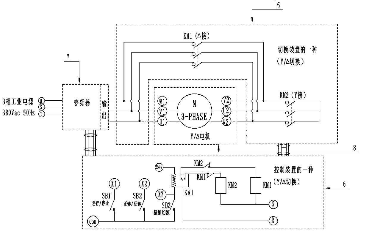
[0049] Such as figure 2 As shown, the star-angle switching device 5 is used to switch the star-angle of the stator winding of the Y / Δ motor 8, the star-angle control device 6 is respectively connected with the star-angle switching device 5 and the frequency converter 7, and the frequency converter 7 is Weihai Maike MV10 series inverter produced by Electric Technology Co., Ltd.

[0050] The star angle switching device 5 includes a delta switch KM1 and a star switch KM2, and the three head ends U1, V1, W1 and the three tail ends U2, V2, W2 of the stator winding on the Y / Δ motor 8 pass through the delta switch KM1 is connected, and the three tail ends U2, V2 and W2 of the stator winding on the Y / Δ motor 8 are connected to the star switch KM2. The voltage output terminal of the frequency converter 7 is connected to the three first terminals U1 , V1 , W1 of the stator winding of the Y / Δ motor 8 . When the angle switch KM1 is closed and the star connection switch KM2 is off, the ...

Embodiment 2

[0078] Such as Figure 5 As shown, the series-parallel switching device 9 is used for series-parallel switching of the stator winding of the motor 12, and the series-parallel control device 10 is used to control the action of the series-parallel switching device 9 and the frequency converter 11. The frequency converter 11 is selected from Weihai Maike Electric Technology Co., Ltd. MV10 series inverters produced by the company.

[0079] The AC380V power supply is connected to the input terminal of the frequency converter 7 .

[0080] The stator winding of the motor 12 is designed to have 9 taps to realize the winding in series and parallel, that is to say, the one-way connection method in the prior art is changed to two-way connection method to lead out the terminals respectively, and the three heads of the one-way winding are U1, V1 , W1, the three tails are U2, V2, W2; the three heads of the other winding are U3, V3, W3, and the three tails are U4, V4, W4.

[0081] Such as ...


PUM

PropertyMeasurementUnit
Lengthaaaaaaaaaa
Lengthaaaaaaaaaa

Abstract

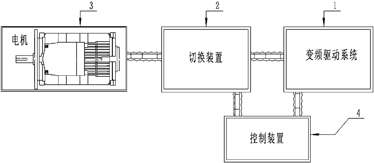
The invention relates to a multi-base-frequency and multi-power switching motor and a driving system. An existing numerical control machine tool main shaft motor or an electric car motor can not simultaneously satisfy requirements of a low speed and a large torque, and a high speed and large power. By using the motor and the system, the above technical problem is solved. A frequency conversion driving system, a switching device, the motor and a control device are included. The frequency conversion driving system is used for driving the motor to work and carrying out frequency conversion speedregulation. The switching device is used for switching working modes of the motor. The control device is used for controlling motion of the switching device and the frequency conversion driving system. The motor and the system are widely used in technical fields of a numerical control machine tool, an electric car and the like.

Description

technical field [0001] The invention relates to a motor drive and control system, in particular to a multi-base frequency multi-power switchable motor and a drive system. Background technique [0002] At present, the spindle motors of CNC machine tools (including electric spindles, frequency conversion motors, and permanent magnet servo motors) mainly use conventional motors with a base frequency (rated frequency) of 50 Hz, and some products use motors with other base frequency values. The main requirements for the electric spindle are: [0003] (1) Sufficient output power: The spindle of the CNC machine tool should be adapted to the processing of various workpieces, there are light loads and heavy loads, but most of the heavy loads are carried out at low speeds, which require sufficient torque and power output; [0004] (2) A certain range of speed regulation: In order to ensure that the CNC machine tool is suitable for various tools, processing materials and processing te...

Claims


Application Information

Patent Timeline
IPC IPC(8): H02P27/04H02P25/18
CPCH02P27/04H02P25/184H02P25/188
Inventor 邓观贞王准姜世利
Owner WEIHAI POLY LIWEI MOTORS CO LTD
Learn More