Thumb far knuckle driver

A driver and thumb technology, applied in the field of micro-device, can solve the problems of high price, complicated system and difficult maintenance

Inactive Publication Date: 2018-03-06
苏茂
View PDF4 Cites 3 Cited by
  • Summary
  • Abstract
  • Description
  • Claims
  • Application Information

AI Technical Summary

Problems solved by technology

[0003] The purpose of the present invention is to solve the disadvantages of the existing force feedback data gloves, such as high price, complex system, and difficult maintenance, and proposes a combination of an external potentiometer and a joint bidirectional active drive device, which can detect the motion information of human hand joints. At the same time, it also converts the feedback force sensory information into a force or torque that directly acts on the human hand, which greatly simplifies the complex force feedback data glove system

Method used


Image

  • Thumb far knuckle driver
  • Thumb far knuckle driver
  • Thumb far knuckle driver

Examples


specific Embodiment approach 1

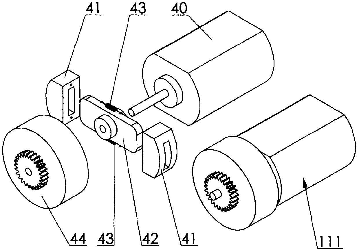
[0007] Specific implementation mode one: as image 3 As shown, the thumb far knuckle driver includes a driving part 111, and the driving part 111 includes a motor 40 and a clutch device, and the clutch device is composed of a clutch device friction plate 41, a friction plate slide bar 42, a return tension spring 43, The clutch device cover 44 is composed of the friction disc slide bar 42 fixedly connected to the shaft of the motor 40, the two clutch device friction discs 41 are inserted into the two ends of the friction disc slide bar 42 respectively, and the two clutch device friction plates 41 are connected with a return Extension spring 43, clutch device cover 44 is inserted into the shaft of motor 40, is sliding contact between the shaft of clutch device cover 44 and motor 40, and clutch device cover 44 is provided with transmission gear. Action implementation process: when the rotation speed of the motor 40 is higher than a certain value, the two friction plates 41 of the...

specific Embodiment approach 2

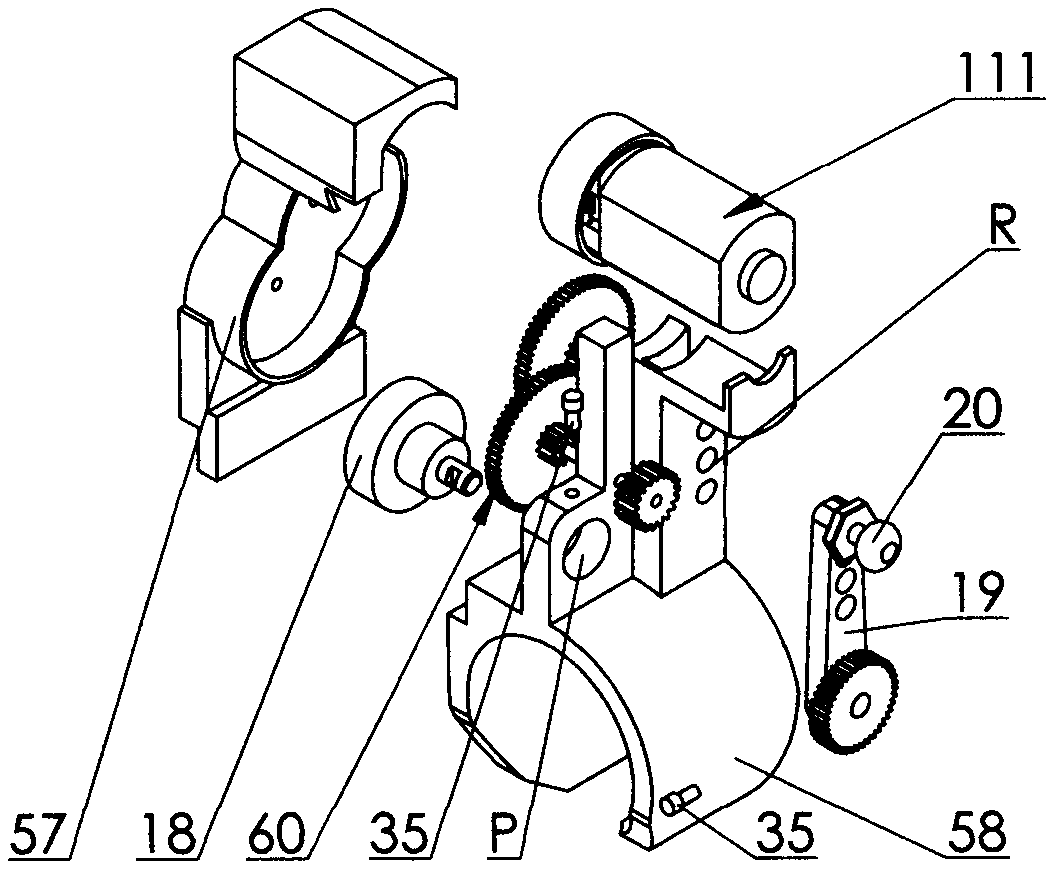
[0008] Specific implementation mode two: as figure 2 and image 3 As shown, the joint detection driving mechanism 100 includes a driving component 111 , a potentiometer 18 , a rocker arm 19 , a gear case cover 57 and a knuckle base 58 . The knuckle base 58 is provided with a hole seat P and a row of mounting holes R for the screws 24, the potentiometer 18 is fixed in the hole seat P of the knuckle base 58 by screws 36, the hole seat The shaft of the potentiometer 18 in the P is fixedly connected with the rocker arm 19 by a screw 35, the gear axis on the rocker arm 19 coincides with the axis of the rocker arm rotation, and the gear of the rocker arm 19 passes through the reduction gear set 60. Cooperate with the gear of the driving part 111 , the driving part 111 is installed on the knuckle base 58 , and the other end of the rocker arm 19 is fixedly connected to the ball head 20 .

specific Embodiment approach 3

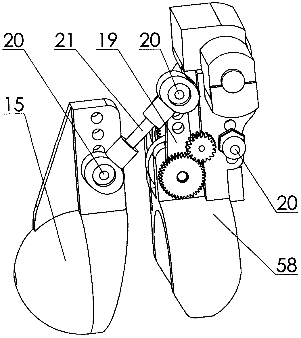
[0009] Specific implementation mode three: as figure 1 , figure 2 and image 3 As shown, the far knuckle base 15 is fixed on the far knuckle position of the human hand. One end of the far knuckle base 15 is cylindrical surrounding the far knuckle, and the other end is hemispherical. The longitudinal section of the whole base It is "U"-shaped, with the opening facing the distal interphalangeal joint (DIP), and a rocker arm is arranged at the position where the base is located on the back of the far knuckle, and the rocker arm is perpendicular to the back of the knuckle where it is located. The rocker arm 19 of the joint detection drive mechanism 110 at the middle phalanx is connected to the base 15 of the distal phalanx through a spherical hinge that cooperates with a ball joint 20 and a ball joint connecting rod 21 . Action implementation process: When the operator’s distal interphalangeal joint (DIP) performs flexion and extension movements, the distal knuckle base 15 atta...


PUM


Abstract

The invention discloses a thumb far knuckle driver which relates to a micro device having a two-way torque feedback function. To solve the problems that a joint measuring mechanism and a force feedback mechanism of an existing force feedback device are separated, a system is complicated, a structure is complex, the maintenance is difficult and two-way active driving cannot be realized and the costis high, the joint detection mechanism and the force feedback mechanism are integrated, and by adopting a unique connecting mode and smart joint measuring point layout, when an operator uses the thumb far knuckle driver, detected fingers can be kept flexible to the full extent and motion states can be precisely detected, so that corresponding finger joints of a controlled slave hand can act withcorresponding finger joints of the operator synergistically, the stress situation of the slave hand in a specific working environment can be fed back to the operator, and the presence sensation of virtual reality or remote operation are improved.

Description

technical field [0001] The invention relates to a micro-device with two-way torque feedback, which is mainly used for the control of a manipulator imitating a human hand. Background technique [0002] Due to the development of science and technology, robots are gradually being used in an increasing range. As a reliable and mature robot, teleoperation robots are widely used in various dangerous, complex and inaccessible environments. It uses a very reliable control method, which is directly controlled by the operator's instructions. As the tasks performed by teleoperated robots become more and more complex, people put forward higher requirements for their flexibility while pursuing reliability, and it is necessary to implement teleoperation on complex manipulators to control the movement of multiple fingers of the manipulator. Multiple joints move together to achieve specific functions, which requires the use of data gloves, and the data glove with force feedback function is...

Claims


Application Information

Patent Timeline
Patent Type & Authority Applications(China)
IPC IPC(8): B25J9/18B25J13/08
CPCB25J9/1612B25J9/1633B25J13/084B25J13/085
Inventor 苏茂
Owner 苏茂
Why Eureka
Try Eureka