Arched and cable-stayed combination type system bridge and construction method thereof

A construction method and system technology, applied in the direction of bridges, bridge parts, bridge construction, etc., can solve problems such as unfavorable load effects on arch feet, substructures and foundations, unsatisfactory technical solutions, and difficult construction techniques, etc., to achieve the elimination of unfavorable influence, reduce the difficulty of design and construction, and reduce the effect of section size and material consumption

Active Publication Date: 2018-03-06
JIANGSU UNIV OF SCI & TECH
View PDF9 Cites 9 Cited by
  • Summary
  • Abstract
  • Description
  • Claims
  • Application Information

AI Technical Summary

Problems solved by technology

[0004] The advantage of the arch bridge is that compared with the beam bridge with the same span, the bending moment and deformation of the arch bridge are much smaller. The advantages of strong compressive capacity, at the same time, the arch bridge has a large spanning capacity and a more beautiful appearance; the disadvantage of the arch bridge is that under the action of the vertical load, the arch bridge has a large horizontal thrust at the arch foot position, It is because of the existence of the horizontal thrust that the moment effect caused by the load in the main arch of the arch bridge is offset. However, due to the horizontal thrust, it brings unfavorable load effects to the arch foot, the substructure and the foundation. The bridge piers and the substructure at the arch foot must bear a large horizontal thrust, which brings great difficulties and challenges to the construction and structure
[0005] In order to eliminate the adverse effects of the strong horizontal thrust of the arch bridge, an arch-beam composite system bridge appeared. In the arch-beam composite system bridge, the beam and the arch are the main load-bearing structures. Together, the horizontal thrust of the arch is transmitted to the beam to bear, eliminating the unfavorable horizontal thrust effect of the arch foot, but in this way, the main beam not only bears dead load and live load, but also bears horizontal tension. The stress state, the stress state is complex, which brings great challenges to the design and construction, and the construction technology is difficult
[0006] Therefore, the horizontal thrust generated at the arch foot of the arch bridge is an unfavorable factor for the popularization and application of the arch bridge, and the existing arch-girder composite system bridge is not ideal in terms of technical solutions. How to reasonably eliminate the horizontal thrust of the arch bridge effect, to obtain an arch-composite system bridge structure with good mechanical performance requires continuous in-depth research and further improvement

Method used


Image

  • Arched and cable-stayed combination type system bridge and construction method thereof
  • Arched and cable-stayed combination type system bridge and construction method thereof
  • Arched and cable-stayed combination type system bridge and construction method thereof

Examples


Embodiment 1

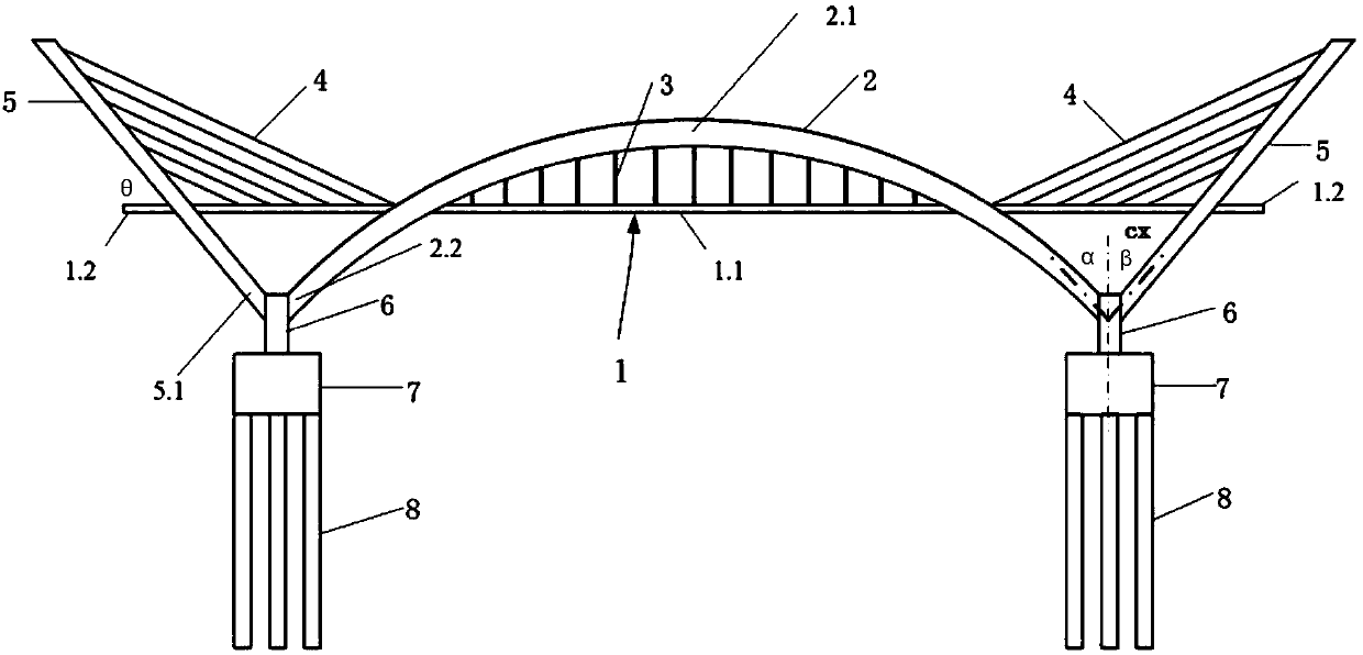
[0041] A bridge with arch and cable-stayed composite system, such as figure 1 , figure 2 and image 3 As shown, it is a three-span structure, including two side spans and a middle span. The middle span is supported by a mid-span arch rib 2. And the stay cable anchor tower column 5 becomes the load-bearing structure of the whole bridge. The section of the bridge deck 1 between the two sections of the arch rib is the middle span 1.1, and the road surface beyond the two ends of the arch rib is the side span 1.2. A suspender 3 is arranged between the passage surface of the bridge deck and a part of the arch ribs above the passage surface, and the bridge deck is fixed on the arch rib 2 through the suspender 3 .

[0042] It is worth noting that the two arch ribs can be provided with transverse connecting members in the transverse direction, or the two arch ribs can adopt separate arch ribs or basket-type arch ribs. The arch rib adopts structural forms such as reinforced concret...

Embodiment 2

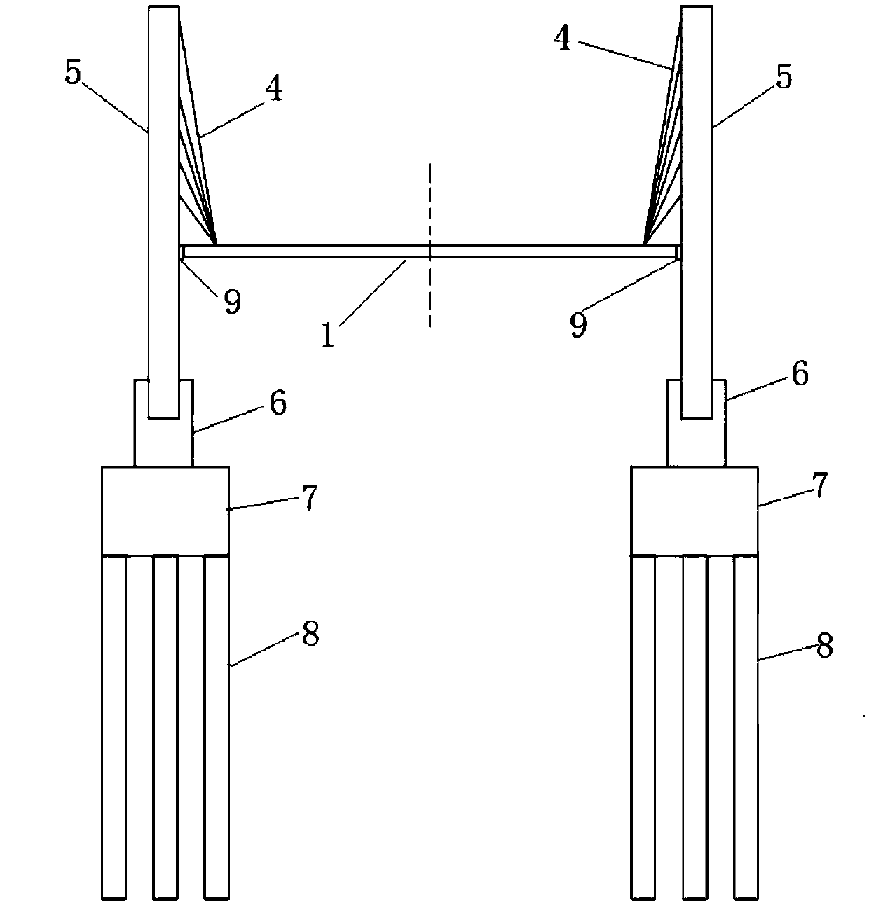
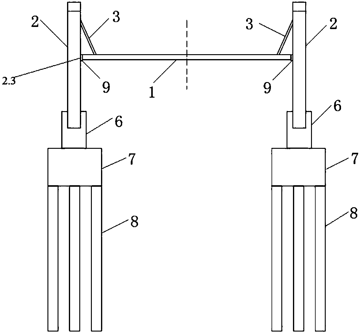
[0049] A bridge with arch and cable-stayed composite system, such as Figure 4 , Figure 5 and Figure 6 As shown, it is a three-span structure, including two side spans and a middle span. The middle span is supported by a mid-span arch rib 2. And the stay cable anchor tower column 5 becomes the load-bearing structure of the whole bridge. The section of the bridge deck 1 between the two sections of the arch rib is the middle span 1.1, and the road surface beyond the two ends of the arch rib is the side span 1.2. A suspender 3 is arranged between the passage surface of the bridge deck and a part of the arch ribs above the passage surface, and the bridge deck is fixed on the arch rib 2 through the suspender 3 .

[0050] It is worth noting that the two arch ribs can be provided with transverse connecting members in the transverse direction, or the two arch ribs can adopt separate arch ribs or basket-type arch ribs. The arch rib adopts structural forms such as reinforced concr...


PUM


Abstract

The invention discloses an arched and cable-stayed combination type system bridge and a construction method. The arched and cable-stayed combination type system bridge comprises at least three spans,which are two side spans and at least one middle span, the middle span is supported by adopting a mid-supported arch rib and booms, a bridge deck is located in the middle of the elevation of the archrib, the arch rib is located outside the bridge deck and is not connected to the bridge deck, the bridge deck below the arch rib is supported by the booms that are connected with the arch rib, the bridge deck above the two side spans and the arch rib of the middle span is supported by adopting cable stays, the bearing structure of the bridge is the mid-supported arch rib of the middle span and thecable stays and pylon pillars of the side spans, the cable stays and the pylon pillars, and arch feet of the arch rib are located in the same vertical plane in the bridge direction, the cable stays and the pylon pillars are obliquely arranged towards the outer sides of the side spans of the bridge from pillar bottoms to pillar tops in the same vertical plane, and the pillar bottoms of the pylon pillars are correspondingly connected with the arch feet of the arch rib.

Description

technical field [0001] The invention belongs to the field of bridge engineering, and in particular relates to an arch-cable-stayed composite system bridge and a construction method thereof. Background technique [0002] There are many types of bridges that people have seen so far. They are all gradually developed through long-term engineering practice and continuous technological innovation in the long-term production and life of human beings. According to the different mechanical characteristics of the bridge structure, the existing bridges can be divided into five basic types, namely: (1) girder bridge, the bridge whose main girder mainly bears the bending load; (2) arch bridge, the main arch bridge The bridge mainly bears the load under compression; (3) Rigid frame bridge, the beam and the column are rigidly connected. Between the bridge and the arch bridge; (4) Suspension bridge, the bridge with the main cable tensioned to bear the external load; (5) Cable-stayed bridg...

Claims


Application Information

Patent Timeline
Patent Type & Authority Applications(China)
IPC IPC(8): E01D12/00E01D19/00E01D21/00E01D21/10
Inventor 蔺满强周道传娄晓阳张祖国巩可陆科成
Owner JIANGSU UNIV OF SCI & TECH
Why Eureka
Try Eureka