
Structure and method for controlling expansion of main oven walls of heat recovery coke oven

A technology of heat recovery and main furnace, which is applied in the direction of coke oven expansion/shrinkage prevention, etc., and can solve the problems of limited influence on the overall service life of the coke oven, cracking of brick joints, etc.

Pending Publication Date: 2021-09-14
辽宁科技大学工程技术有限公司
View PDF1 Cites 1 Cited by
  • Summary
  • Abstract
  • Description
  • Claims
  • Application Information

AI Technical Summary

Problems solved by technology

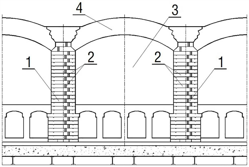
The main furnace wall in the prior art does not have expansion joints, and the expansion joints are generally arranged at the quadruple arches and the furnace bottom to absorb the longitudinal expansion of the entire coke oven. The expansion of the main furnace wall with this structure will Longitudinal expansion occurs in the direction of the carbonization chamber, which produces a large horizontal thrust on the vault, causing thermal vertical expansion and deformation of the vault. The thermal expansion of the vault will lead to serious defects such as cracking of the brick joints at the center of the central furnace top.
The Chinese invention patent with the application number 201710718036.7 discloses a liquid grouting material for thermal repair of coke oven wall cracks and its preparation method, which is a liquid grouting material for thermal repair of coke oven wall cracks, but this late The repair has very limited impact on the overall life and operating efficiency of the coke oven, and cannot fundamentally solve the cracking problem of the furnace roof caused by the thermal expansion of the main furnace wall

Method used


Image

  • Structure and method for controlling expansion of main oven walls of heat recovery coke oven
  • Structure and method for controlling expansion of main oven walls of heat recovery coke oven

Examples


Embodiment Construction

[0018] Below in conjunction with embodiment technical scheme of the present invention will be further described:

[0019] In the description of the present invention, it should be noted that unless otherwise specified and limited, the terms "installation", "connection" and "connection" should be understood in a broad sense, for example, it can be a fixed connection or a detachable connection. Connected, or integrally connected; either directly or indirectly through an intermediary. Those of ordinary skill in the art can understand the specific meanings of the above terms in the present invention in specific situations.

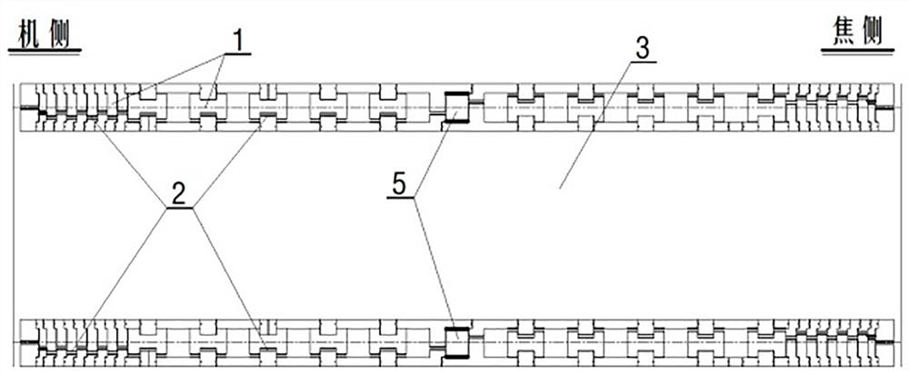
[0020] See Figure 1 ~ Figure 2 , is a structural schematic diagram of a heat recovery coke oven according to the present invention to control the expansion of the main furnace wall structure. Expansion joints are arranged on the main furnace walls on both sides of the carbonization chamber along the machine side to the coke side. The expansion joints are res...


PUM


Abstract

The invention belongs to the technical field of clean heat recovery coke ovens in the metallurgical industry, and particularly relates to a structure and a method for controlling the expansion of main oven walls of a heat recovery coke oven. The structure is characterized in that expansion gaps are arranged in the main oven walls on two sides of a carbonization chamber from a machine side to a coke side, the width direction of the expansion gaps is perpendicular to a machine-coke direction, the reserved width of the expansion gaps is 5-15 mm, and the expansion gaps are used for eliminating longitudinal thermal expansion of the main oven walls at a temperature of 1000-1650 DEG C. The structure and the method of the invention have the advantages that: 1) the longitudinal expansion of the carbonization chamber when the main oven walls are heated is effectively controlled, a brick joint at the center of the top of the oven is not cracked any more, and the service life of the coke oven is prolonged; 2) the expansion gaps are filled with elastic fire clay, so the longitudinal expansion amounts of the main oven walls can be absorbed, and gas inter-leakage between flame paths can be well prevented; and 3) longitudinal braces of the coke oven can be completely omitted, so construction investment is saved, and meanwhile preconditions are created for reasonable arrangement of a control system on an oven top.

Description

technical field [0001] The invention belongs to the technical field of clean heat recovery coke ovens in the metallurgical industry, and in particular relates to a structure and method for controlling the expansion of a main furnace wall of a heat recovery coke oven. Background technique [0002] In the long-term use of the coke oven, the temperature impact of the sudden change of cold and heat caused by operations such as opening and closing the furnace door, coal charging and coke discharge has the greatest impact on the furnace body. The main furnace wall in the prior art does not have expansion joints, and the expansion joints are generally arranged at the quadruple arches and the bottom of the furnace to absorb the longitudinal expansion of the entire coke oven. The expansion of the main furnace wall with this structure will Longitudinal expansion occurs in the direction of the carbonization chamber, which produces a large horizontal thrust on the vault, causing thermal...

Claims


Application Information

Patent Timeline
IPC IPC(8): C10B29/04
CPCC10B29/04
Inventor 邹力杨丽云
Owner 辽宁科技大学工程技术有限公司
Learn More