
Double-curve pipe force valve

A hyperbolic and curved technology, which is applied in the field of hyperbolic pipe force valves, can solve the problems of bending deformation of the ejector pin, only tilting setting, and large flow channel resistance of the valve body, so as to achieve the effect of preventing bending deformation and increasing the minimum

Pending Publication Date: 2018-12-11
YUANDA VALVE GRP CO LTD
View PDF1 Cites 0 Cited by
  • Summary
  • Abstract
  • Description
  • Claims
  • Application Information

AI Technical Summary

Problems solved by technology

Since the chute is a rotating motion, it produces vertical thrust and horizontal thrust on the ejector rod, and the horizontal thrust will cause the ejector rod to bend and deform, resulting in the ejector rod not moving up and down, and the valve cannot work normally. In addition, the seal on the edge of the eccentric large disc The vice can only be set at an incline, the resistance of the flow channel of the valve body is large, the energy consumption is high, and the processing is difficult and costly

Method used


Image

  • Double-curve pipe force valve
  • Double-curve pipe force valve
  • Double-curve pipe force valve

Examples


Embodiment Construction

[0030] The present invention will be described in further detail below in conjunction with the accompanying drawings.

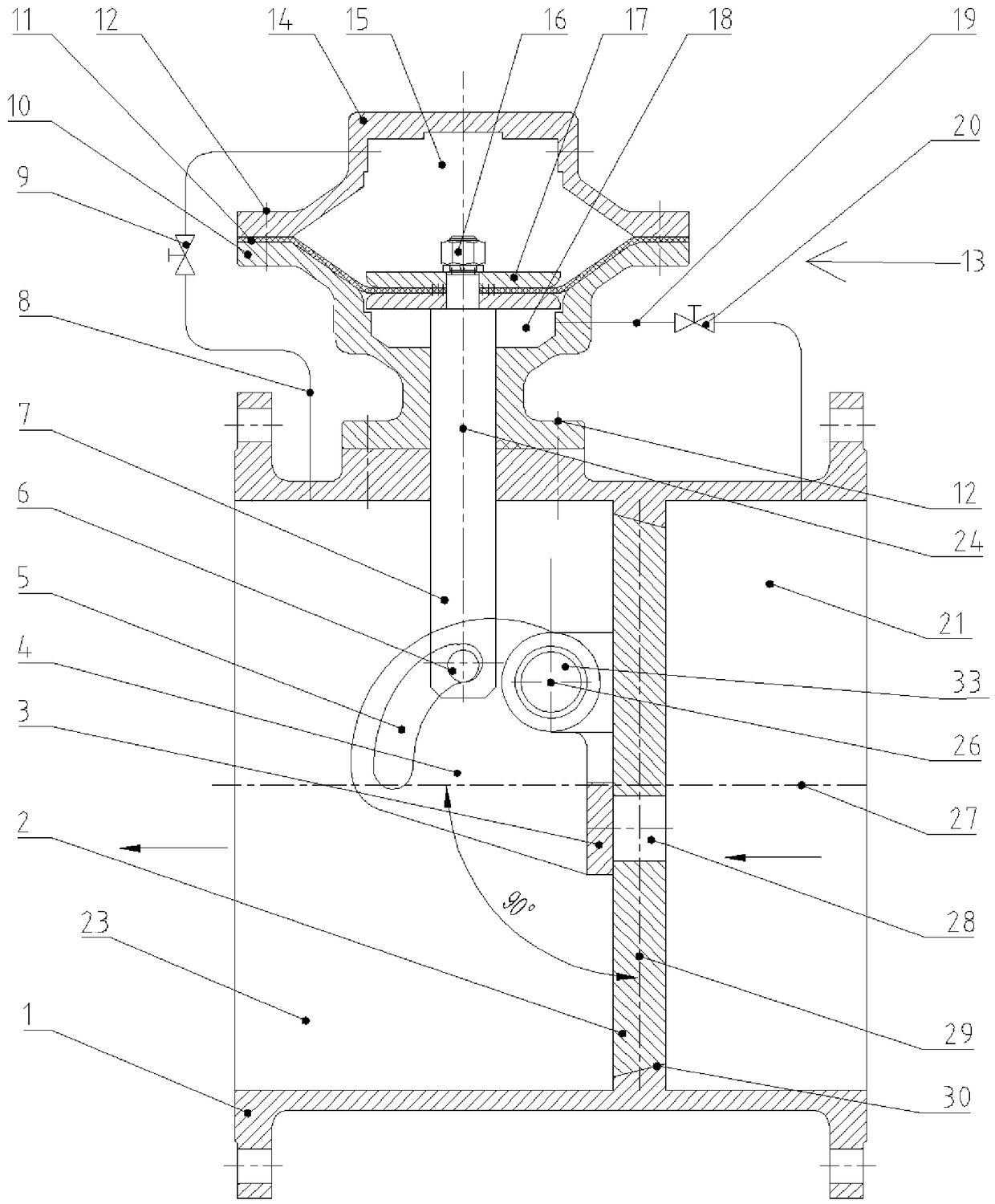
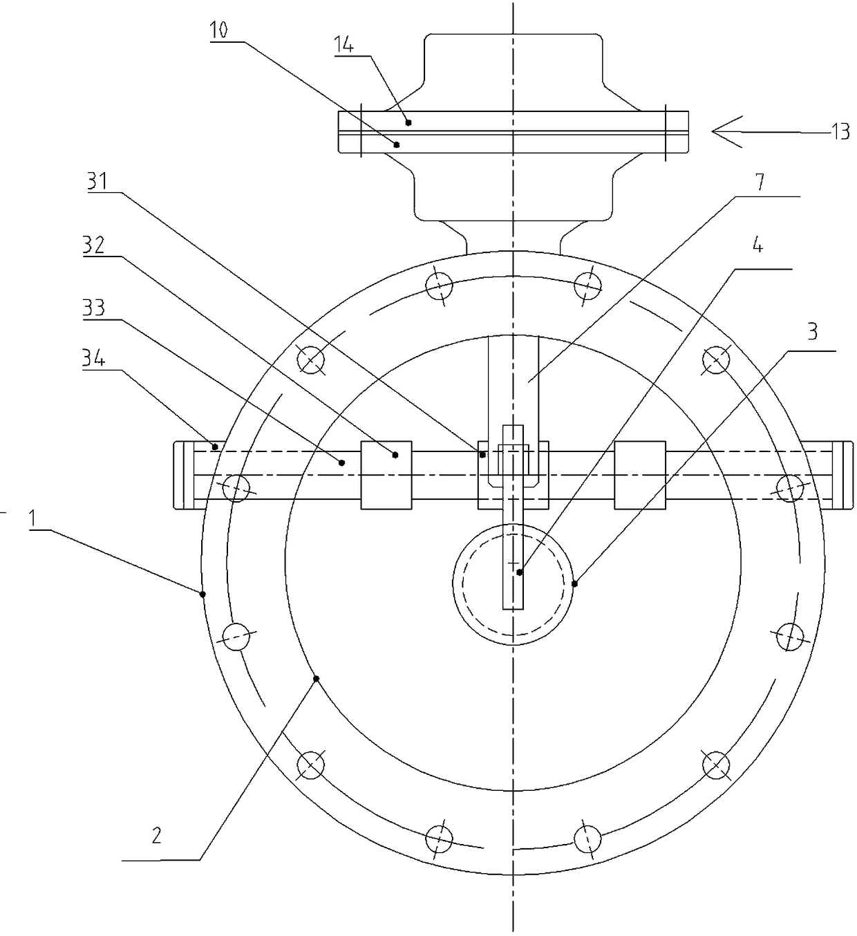
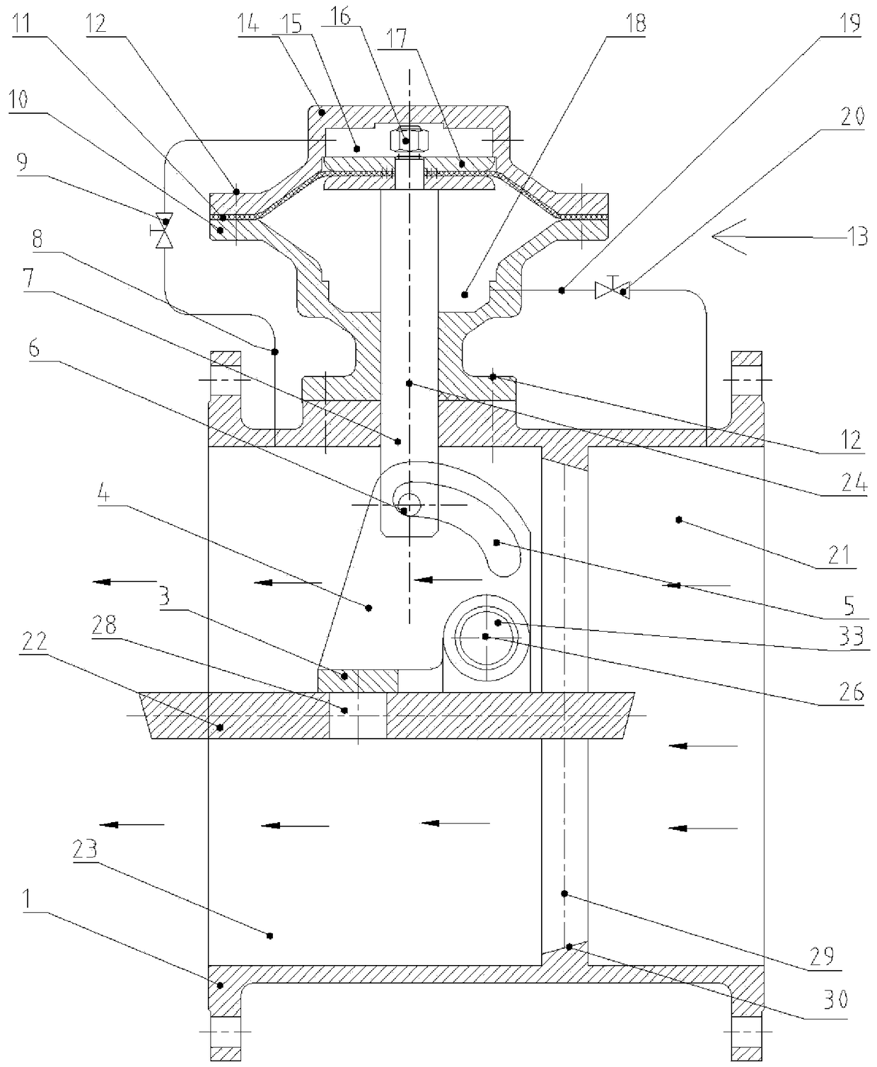
[0031] Such as Figure 1~4 An embodiment of a hyperbolic tube force valve shown includes a valve body 1, a valve body shaft hole 25 opened at the top of the valve body 1, a master control cylinder 13 is provided above the valve body 1, and the main The control cylinder 13 includes an upper cavity 15 and a lower cavity 18. The lower cavity 18 is slidably provided with a mandrel 7, and the lower part of the mandrel 7 extends through the valve body shaft hole 25 into the valve body 1. A pin shaft 6 is provided, and a valve stem 33 is provided in the valve body 1 through a bearing rotation. The valve stem 33 is provided with an eccentric large valve flap 2 and a small valve flap 3 assembly, and the eccentric large valve flap 2 passes through the large The valve disc sleeve 32 is suspended and fixed on the valve stem 33, and rotates with the valve stem 33, and divid...


PUM


Abstract

The invention relates to a double-curve pipe force valve which comprises a valve body, a main control cylinder, an ejector rod, a valve rod, an eccentric large valve clack and a small valve clack assembly. The main control cylinder comprises an upper cavity and a lower cavity. The lower portion of the ejector rod extends into the valve body to be provided with a pin shaft. The eccentric large valve clack is arranged on the valve rod in a suspended manner, and a runner of the valve body is divided into an inlet end and an outlet end. The inlet end communicates with the lower cavity through a first bypass assembly, and the outlet end communicates with the upper cavity through a second bypass assembly. The small valve clack assembly comprises a small valve clack crank rotationally arranged onthe valve rod and a small valve clack arranged on the lower portion of the small valve clack crank. A double-curve sliding groove is formed on the upper portion of the small valve clack crank. The pin shaft penetrates through the double-curve sliding groove and is in sliding connection along the double-curve sliding groove. According to the double-curve pipe force valve, the horizontal thrust ofthe sliding groove to the ejector rod can be eliminated, bending deformation of the ejector rod can be avoided, and the valve can stably work for a long time.

Description

Technical field [0001] The invention relates to a water pump control valve, in particular to a hyperbolic tube force valve. Background technique [0002] The pipe valve is mainly used in the outlet pipe of the automatic water supply and drainage pumping station. It can be applied to clean water, raw water and sewage, slurry water and other media. The pipe valve has a compact structure, small volume and light weight, and is especially suitable for large-diameter pipes. Road system. It can be widely used in the transportation system of electric power, environmental protection, metallurgy, petrochemical, water department, municipal administration, food and other industries, such as water supply and drainage systems, sewage pump houses, and chemical fluids. [0003] In the prior art, for example, a tube power valve disclosed in Chinese Patent Application 201120566351.0, the tube power valve has a straight-line sliding groove on the small disc crank. When the valve is opened, the small...

Claims


Application Information

Patent Timeline
Patent Type & Authority Applications(China)
IPC IPC(8): F16K1/20F16K1/36F16K1/46F16K31/36
CPCF16K1/2021F16K1/2028F16K1/36F16K1/465F16K31/36
Inventor 米红娟冯玉柱何春焕杜立伟王迎涛邵建农李巧荣
Owner YUANDA VALVE GRP CO LTD
Learn More