L-shaped concrete retaining wall

A technology for concrete and retaining walls, applied in the field of building materials, can solve the problems such as the inability to reuse the formwork, multi-site construction personnel, and the threat of the stability of the retaining wall, so as to reduce the sudden rise of the groundwater level, the connection effect is good, and the structural design is ingenious. Effect

Pending Publication Date: 2018-03-06
ANHUI JIANHUA CONCRETE PILE
View PDF10 Cites 7 Cited by
  • Summary
  • Abstract
  • Description
  • Claims
  • Application Information

AI Technical Summary

Problems solved by technology

Since the wall of the concrete retaining wall structure is a whole piece of poured wall, when the wall is made, it cannot be poured until the steel bars are erected. The entire construction period is long, and the wall pouring requires more on-site construction personnel The amount of physical labor is large, the cost of construction labor is high, and the formwork cannot be reused. On the one hand, the material is wasteful, and on the other hand, the construction efficiency is not high
Secondly, the structure of the retaining wall is closely related to the material of the backfilling body and the groundwater level, especially in the event of heavy rainfall, as the groundwater level of the backfilling body rises sharply, it will affect the stability of the retaining wall. sexual threat

Method used


Image

  • L-shaped concrete retaining wall
  • L-shaped concrete retaining wall
  • L-shaped concrete retaining wall

Examples


Embodiment

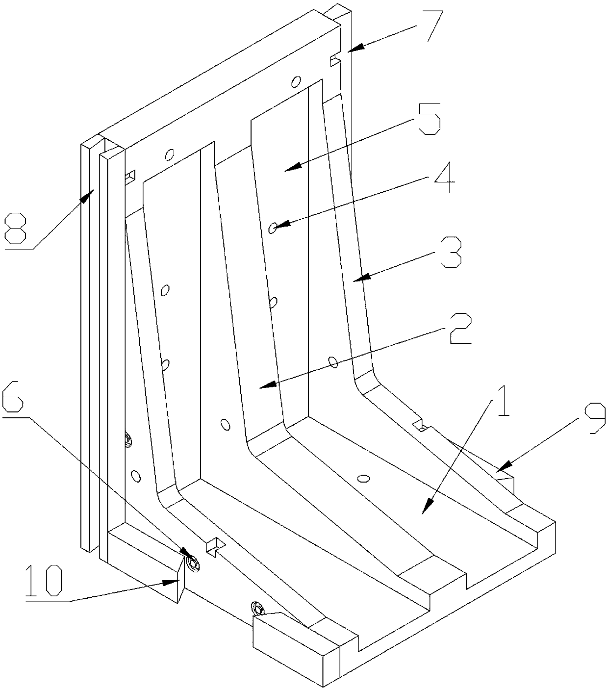
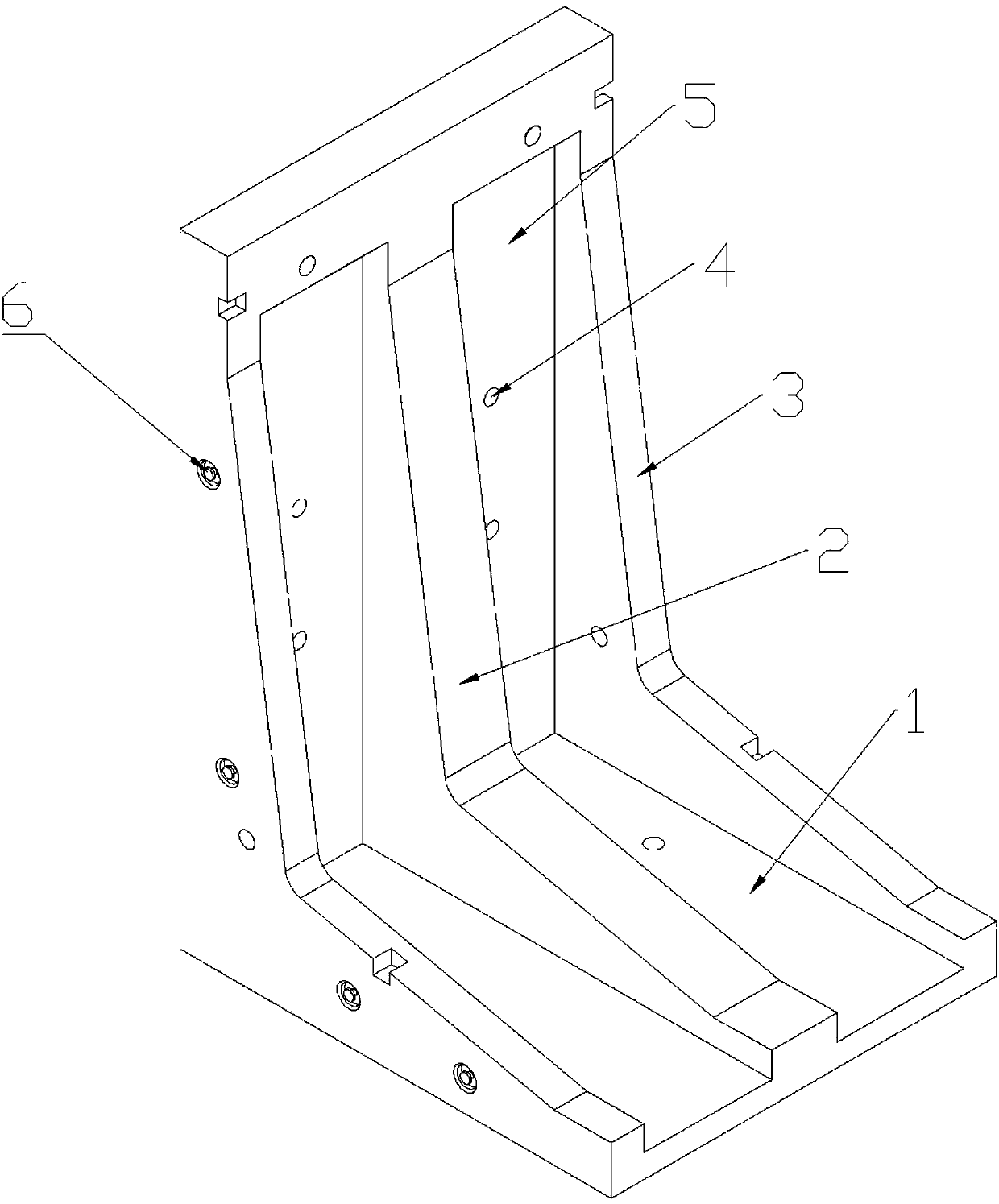
[0025] The vertical plate 5, the bottom plate 1, the main rib plate 2 and the side rib plate 3 are an integrally formed structure in which the steel skeleton is poured with concrete in a mold. Modular prefabrication is implemented, which is small in size, convenient in transportation, and easy to assemble. Compared with traditional Formwork is set up on the construction site to set up steel bars and then pour the wall. The present invention is more convenient to use. In actual construction, multiple L-shaped concrete retaining walls pass through the first tenon 7 of one retaining wall and the first tenon and groove of the next retaining wall. 8 cooperate with each other and the second mortise 9 of one retaining wall cooperates with the second mortise 10 of the next retaining wall to make multiple concrete retaining walls integrated, thus making the retaining wall more stable as a whole.

[0026] Further, the vertical plate 5, the bottom plate 1, the main rib plate 2 and the sid...


PUM


Abstract

The invention discloses an L-shaped concrete retaining wall comprising a body part and a tenon-and-mortise part. The body part comprises a base plate, a main rib plate, a vertical plate and two side rib plates. The vertical plate, the main rib plate and the side rib plates are arranged on the base plate. The main rib plate is located in the middle of the upper surface of the base plate. The two rib plates are located on the left side and the right side of the main rib plate. The outer side face of each side rib plate coincides with the left side face and the right side face of the base plate.The vertical plate is provided with four water seepage holes. Each side rib plate is provided with a water seepage hole. The tenon-and-mortise part comprises a first tenon, a first mortise, a second tenon and a second mortise. The L-shaped concrete retaining wall achieves modularized prefabrication, concrete and a steel reinforcement framework are formed in a mold in an integrated manner, and connection between the steel reinforcement framework and the concrete is more stable through arranged reinforcing steel bar headings. The water seepage holes are arranged on the vertical plate and the side rib plates and achieve the water seepage function. Due to the tenon-and-mortise design, after construction, multiple concrete retaining walls can be more easily matched, and the stability is higher.

Description

technical field [0001] The invention belongs to the technical field of building materials, in particular to an L-shaped concrete retaining wall. Background technique [0002] Concrete retaining wall is a widely used retaining structure in water conservancy and civil engineering. Concrete retaining wall is a structure that places fill or soil deformation and instability. It is often used in slope treatment, slag yard treatment and other projects. In engineering construction, due to the need for site leveling and elevation control, reinforced concrete retaining walls are often used. The wall of the traditional concrete retaining wall structure is an integral pouring wall, which is generally a retaining wall cast with wooden formwork. The method of making a concrete retaining wall is: first excavate the foundation groove on site, and then lay the cushion, cushion After the pavement is completed, the formwork is erected on the spot to erect the steel bars, and finally the wall ...

Claims


Application Information

Patent Timeline
Patent Type & Authority Applications(China)
IPC IPC(8): E02D29/02E02D17/20
CPCE02D17/20E02D29/0275
Inventor 杨余明邵国纲修雨欣鲁元春
Owner ANHUI JIANHUA CONCRETE PILE
Why Eureka
Try Eureka