Supercharge Your Innovation With Domain-Expert AI Agents!

Gas bag reduction unit

A reducer, air bag type technology, applied in mechanical equipment, springs/shock absorbers, transmission parts, etc., can solve problems such as poor impact resistance, and achieve the effect of improving efficiency, reducing impulse and saving costs

Inactive Publication Date: 2018-03-06
常州蓝黛机械设备有限公司
View PDF0 Cites 0 Cited by
  • Summary
  • Abstract
  • Description
  • Claims
  • Application Information

AI Technical Summary

Problems solved by technology

[0003] In order to overcome the deficiencies of the existing reducer with poor impact resistance, the present invention provides an air bag type reducer

Method used


Image

  • Gas bag reduction unit

Examples


Embodiment Construction

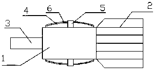
[0009] Such as figure 1 It is a schematic diagram of the structure of the present invention. The air bag type reducer includes a reduction mechanism 1, a motor 2 and a rotating shaft 3. One end of the rotating shaft 3 is placed in the reduction mechanism 1. The motor 2 is fixedly connected to the reduction mechanism 1. The upper and lower ends of the reduction mechanism 1 pass through the The plastic bag 4 is placed in the hanging ring 5 and is fixedly connected with the deceleration mechanism 1. The plastic bag 4 is provided with nitrogen gas, and the upper end of the plastic bag 4 is provided with a hydrophobic nano layer 6.

[0010] After the plastic bag 4 filled with nitrogen is covered on the speed reducer 1, when an external force impacts the speed reducer, it will first collide with the plastic bag 4, thereby slowing down the pressure on the speed reducer 1, and nitrogen can to a certain extent Reduce the temperature on the reduction mechanism 1, so the effect of coolin...


PUM


Abstract

The invention relates to a speed reducer, especially an air bag type speed reducer. The reducer includes a reduction mechanism, a motor and a rotating shaft. One end of the rotating shaft is placed in the reduction mechanism, and the motor is fixedly connected to the reduction mechanism. With nitrogen, the upper end of the plastic bag is provided with a hydrophobic nano-layer. The reducer can provide a certain buffer against external impact, reduce the impact, save costs and improve efficiency.

Description

technical field [0001] The invention relates to a speed reducer, especially an air bag type speed reducer. Background technique [0002] There is only one connection between the reduction mechanism of the current reducer and the motor. This connection structure is not very firm, and it is easy to cause damage to the body when encountering an external force impact. Contents of the invention [0003] In order to overcome the shortage of poor impact resistance of the existing reducer, the present invention provides an air bag type reducer. [0004] The technical solution adopted by the present invention to solve its technical problems is: an air bag type reducer, including a reduction mechanism, a motor and a rotating shaft, one end of the rotating shaft is placed in the reduction mechanism, the motor is fixedly connected with the reduction mechanism, and the upper and lower ends of the reduction mechanism are passed through a plastic bag. Placed in the hanging ring, fixedly...

Claims


Application Information

Patent Timeline
Patent Type & Authority Applications(China)
IPC IPC(8): F16H57/028F16F15/023
CPCF16H57/028F16F15/023F16F15/0232
Inventor 李少君
Owner 常州蓝黛机械设备有限公司
Features
  • R&D
  • Intellectual Property
  • Life Sciences
  • Materials
  • Tech Scout
  • Unparalleled Data Quality
  • Higher Quality Content
  • 60% Fewer Hallucinations
Learn More