Supercharge Your Innovation With Domain-Expert AI Agents!

Machine vision monitoring equipment

A monitoring equipment and machine vision technology, applied in the field of machine vision monitoring equipment, can solve problems such as unfavorable parts monitoring, inability to move, and blurred images, and achieve the effects of improving work efficiency, fast monitoring work, and slow resolution.

Inactive Publication Date: 2018-03-06
CHENGDU CHENHONG TECH
View PDF0 Cites 2 Cited by
  • Summary
  • Abstract
  • Description
  • Claims
  • Application Information

AI Technical Summary

Problems solved by technology

[0003] However, most of the existing equipment uses ordinary cameras to take pictures and samples of parts. Due to the lens, the acquired images are easy to blur or overexposed, which is not conducive to the monitoring of parts. Monitoring of parts of various specifications

Method used


Image

  • Machine vision monitoring equipment
  • Machine vision monitoring equipment
  • Machine vision monitoring equipment

Examples


Embodiment Construction

[0018] The following will clearly and completely describe the technical solutions in the embodiments of the present invention with reference to the accompanying drawings in the embodiments of the present invention. Obviously, the described embodiments are only some, not all, embodiments of the present invention. Based on the embodiments of the present invention, all other embodiments obtained by persons of ordinary skill in the art without making creative efforts belong to the protection scope of the present invention.

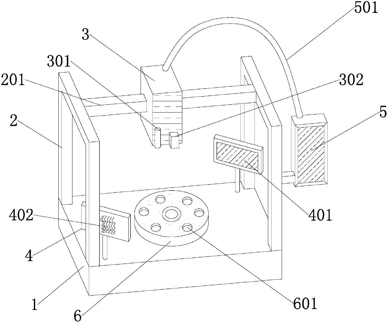
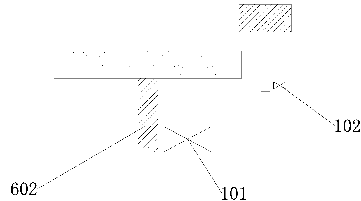
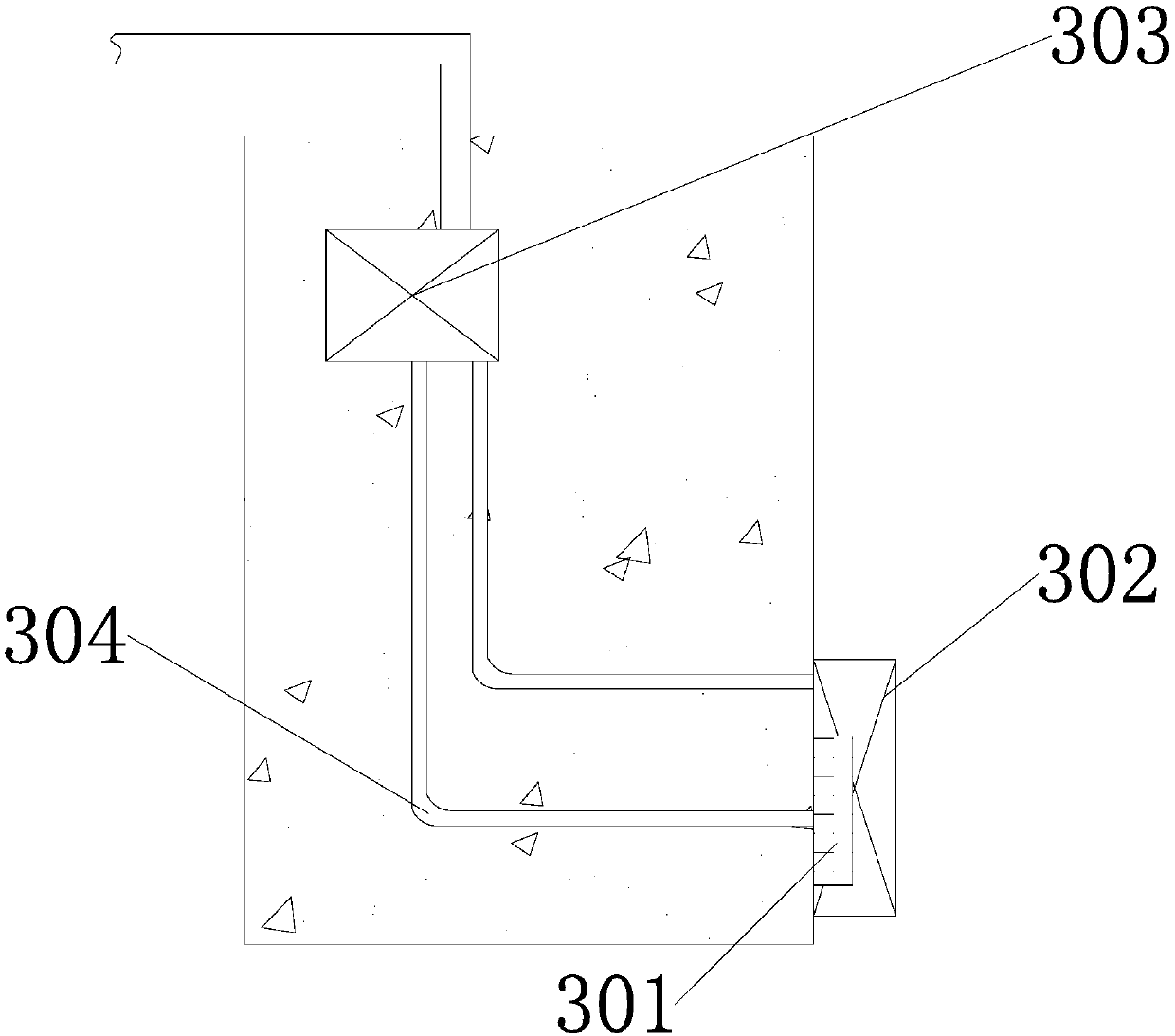
[0019] see Figure 1-3 , the present invention provides a technical solution: a machine vision monitoring device, comprising an equipment base 1 and a bracket 2, a bracket 2 is arranged above the equipment base 1, and the bracket 2 is fixedly connected to the equipment base 1 by bolts, The upper end of the equipment base 1 is provided with a rotating shaft 602, and the rotating shaft 602 is embedded in the equipment base 1. A turntable 6 is arranged above the ...


PUM


Abstract

The invention discloses a machine vision monitoring device, which consists of a device base and a bracket. A bracket is arranged above the device base, and the bracket is fixedly connected to the device base through bolts. In the equipment base, a turntable is arranged above the rotating shaft, and the turntable is rotatably connected in the rotating shaft. A display screen is arranged on the right side of the bracket, and the display screen is fixedly connected in the bracket. An optical cable is arranged above the display screen, and the optical cable is embedded in the display screen. In order to monitor the parts faster, a movable turntable is set in the part placement area. There are six stations on the turntable for placing parts. Through the rotation of the turntable, the monitoring device can monitor multiple parts at a time and then replace them, making the monitoring The work is faster, the work efficiency is improved, and the traditional device is slow in monitoring and needs to replace parts after each monitoring.

Description

technical field [0001] The invention relates to the technical field of monitoring equipment, in particular to a machine vision monitoring equipment. Background technique [0002] The vision system refers to converting the ingested target into an image signal through machine vision products, sending it to a dedicated image processing system, and converting it into a digital signal according to pixel distribution, brightness, color and other information; the image system performs various calculations on these signals. Extracting the characteristics of the target, and then controlling the action of the equipment on the spot according to the result of the discrimination, is a valuable mechanism for production, assembly or packaging. It has inestimable functions in detecting defects and preventing defective products from being delivered to consumers. the value of. [0003] However, most of the existing equipment uses ordinary cameras to take pictures and samples of parts. Due to...

Claims


Application Information

Patent Timeline
Patent Type & Authority Applications(China)
IPC IPC(8): G01C11/02
CPCG01C11/02
Inventor 田震
Owner CHENGDU CHENHONG TECH
Features
  • R&D
  • Intellectual Property
  • Life Sciences
  • Materials
  • Tech Scout
  • Unparalleled Data Quality
  • Higher Quality Content
  • 60% Fewer Hallucinations
Learn More