Check patentability & draft patents in minutes with Patsnap Eureka AI!

Multipath high voltage pulse monitoring device

A high-voltage pulse and monitoring device technology, applied in the direction of pulse characteristic measurement, etc., can solve the problems of high cost, difficult to determine, bulky and so on

Pending Publication Date: 2018-03-06
XI'AN INST OF OPTICS & FINE MECHANICS - CHINESE ACAD OF SCI
View PDF0 Cites 0 Cited by
  • Summary
  • Abstract
  • Description
  • Claims
  • Application Information

AI Technical Summary

Problems solved by technology

[0004] In order to overcome the shortcomings of bulky size, high cost and difficulty in determining the relative time caused by the existing multiple oscilloscopes and multi-channel power attenuators for pulse monitoring, the present invention proposes a highly integrated, simple and convenient multi-channel high-voltage pulse monitoring device

Method used


Image

  • Multipath high voltage pulse monitoring device
  • Multipath high voltage pulse monitoring device

Examples


Embodiment Construction

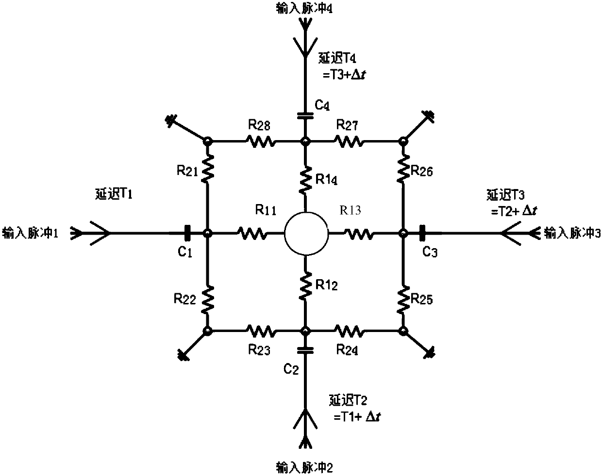
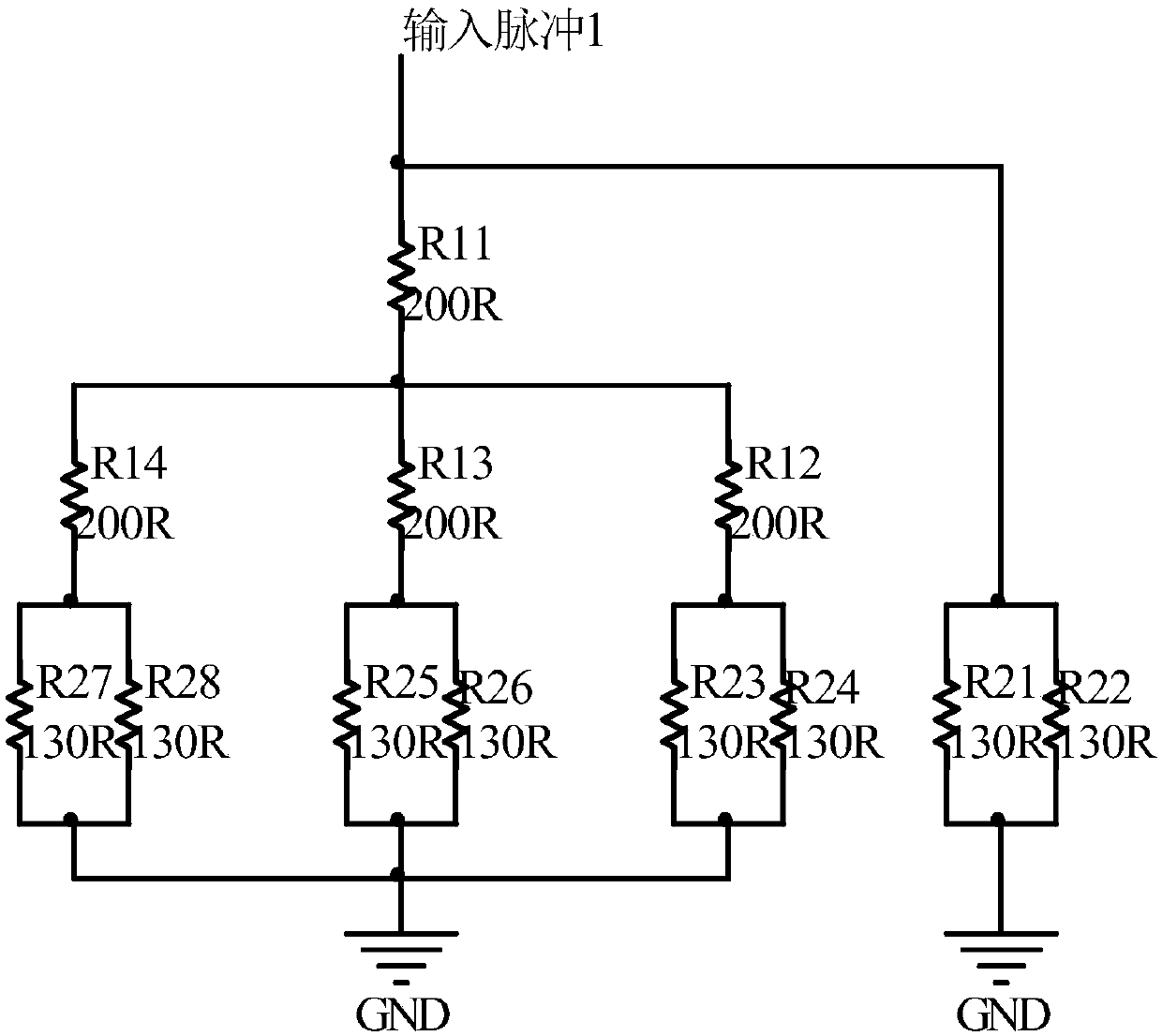
[0019] Such as figure 1 As shown, the input high-voltage pulses enter the system from "input pulse 1", "input pulse 2"...etc., and pass through different delay lines, which are staggered in time. The choice of delay line is determined by the width of the pulse. Generally, in order to achieve For observable pulses, the length of the delay line is selected as the length of the transmission cable corresponding to 3-5 times of the pulse time width. Among them, C1, C2... are to isolate the external DC signal and avoid damage to the terminal oscilloscope. The values ​​of C1, C2... are calculated according to the bandwidth of the pulse. Based on the required attenuation factor and system impedance, calculate the matching resistor value around each input pulse. After delay, matching, and attenuation, multiple pulses are gathered at the center for input. The PCB layout design of the entire circuit is a centrally symmetrical structure, and the wiring length and width of each node with...


PUM


Abstract

The invention provides a highly integrated and simple and convenient multipath high voltage pulse monitoring device. The multipath high voltage pulse monitoring device comprises signal attenuation delay circuits which are independently arranged for being corresponding to each path of high voltage pulse. The output of each signal attenuation delay circuit is accessed to the same monitoring terminal. The corresponding resistance network is configured for each signal attenuation delay circuit according to the required attenuation multiple and the system impedance, and different delay lines are arranged so that all paths of high voltage pulses are enabled to be orderly staggered in the time domain to enter the monitoring terminal in turn. Multipath high voltage pulse monitoring of different impedance and different pulse width can be realized. The multipath high voltage pulse monitoring device can be suitable for monitoring of various multipath and multi-impedance high voltage pulses through extension of the device so as to be widely applied to the field of streak cameras, amplitude phase splitting and X-ray tubes.

Description

technical field [0001] The invention belongs to the technical field of high-power pulses, and relates to a multi-channel high-voltage pulse monitoring circuit. Background technique [0002] For devices using high-voltage pulse sources, the traditional high-voltage pulse monitoring is to connect high-bandwidth and high-power attenuators with different attenuation multiples, and then send them to a high-bandwidth oscilloscope for recording after attenuation. The disadvantage of this solution is that multiple attenuators are required for multiple high-voltage pulses, resulting in a large volume, and it is difficult to observe the relative time of pulse arrival, especially when there are more than 4 signals to be monitored, the existing single oscilloscope cannot meet the required recording The number of channels, multiple oscilloscopes will introduce time uncertainty. [0003] Therefore, there is an urgent need to design a device that is simple, reliable, highly integrated, an...

Claims


Application Information

Patent Timeline
IPC IPC(8): G01R29/02
CPCG01R29/02
Inventor 王博赵卫白永林朱炳利陈震曹伟伟缑永胜白晓红秦君军
Owner XI'AN INST OF OPTICS & FINE MECHANICS - CHINESE ACAD OF SCI
Features
  • R&D
  • Intellectual Property
  • Life Sciences
  • Materials
  • Tech Scout
  • Unparalleled Data Quality
  • Higher Quality Content
  • 60% Fewer Hallucinations
Learn More