
Calculation model-based method for determining inherent strains of laser peening

A technology of laser peening and inherent strain, which is applied in the field of mechanical processing, can solve the problems of complex implementation process, difficulty in obtaining inherent strain in the depth direction, and difficulty in residual stress, so as to improve the efficiency of calculation and simulation, improve accuracy, and simplify measurement Effect

Active Publication Date: 2018-03-06
SHANGHAI JIAO TONG UNIV
View PDF5 Cites 7 Cited by
  • Summary
  • Abstract
  • Description
  • Claims
  • Application Information

AI Technical Summary

Problems solved by technology

Although the inherent strain method has been widely used in the field of welding, it is still relatively scarce in the research of laser peening.
[0005] The existing patent "Method for Determining the Process Parameters of Laser Peening Forming of Complicated Curved Surface Shaped Workpieces" (application number CN201510102659.2) is the first in China to introduce the inherent strain method into the application of laser peening. According to the target surface shape optimization method to select the corresponding laser peening forming process parameters, but how to obtain the inherent strain distribution corresponding to different laser peening parameters is not introduced in this patent
In his paper, American scholar DeWald proposed a method of measuring the residual stress and establishing a semi-analytic formula to reverse the intrinsic strain. However, the implementation process of this method is complicated, and it is difficult to accurately measure the residual stress, and it is difficult to obtain the intrinsic strain in the depth direction.

Method used


Image

  • Calculation model-based method for determining inherent strains of laser peening
  • Calculation model-based method for determining inherent strains of laser peening
  • Calculation model-based method for determining inherent strains of laser peening

Examples


Embodiment Construction

[0032] The present invention will be described in detail below in conjunction with specific embodiments. The following examples will help those skilled in the art to further understand the present invention, but do not limit the present invention in any form. It should be noted that those skilled in the art can make several changes and improvements without departing from the concept of the present invention. These all belong to the protection scope of the present invention.

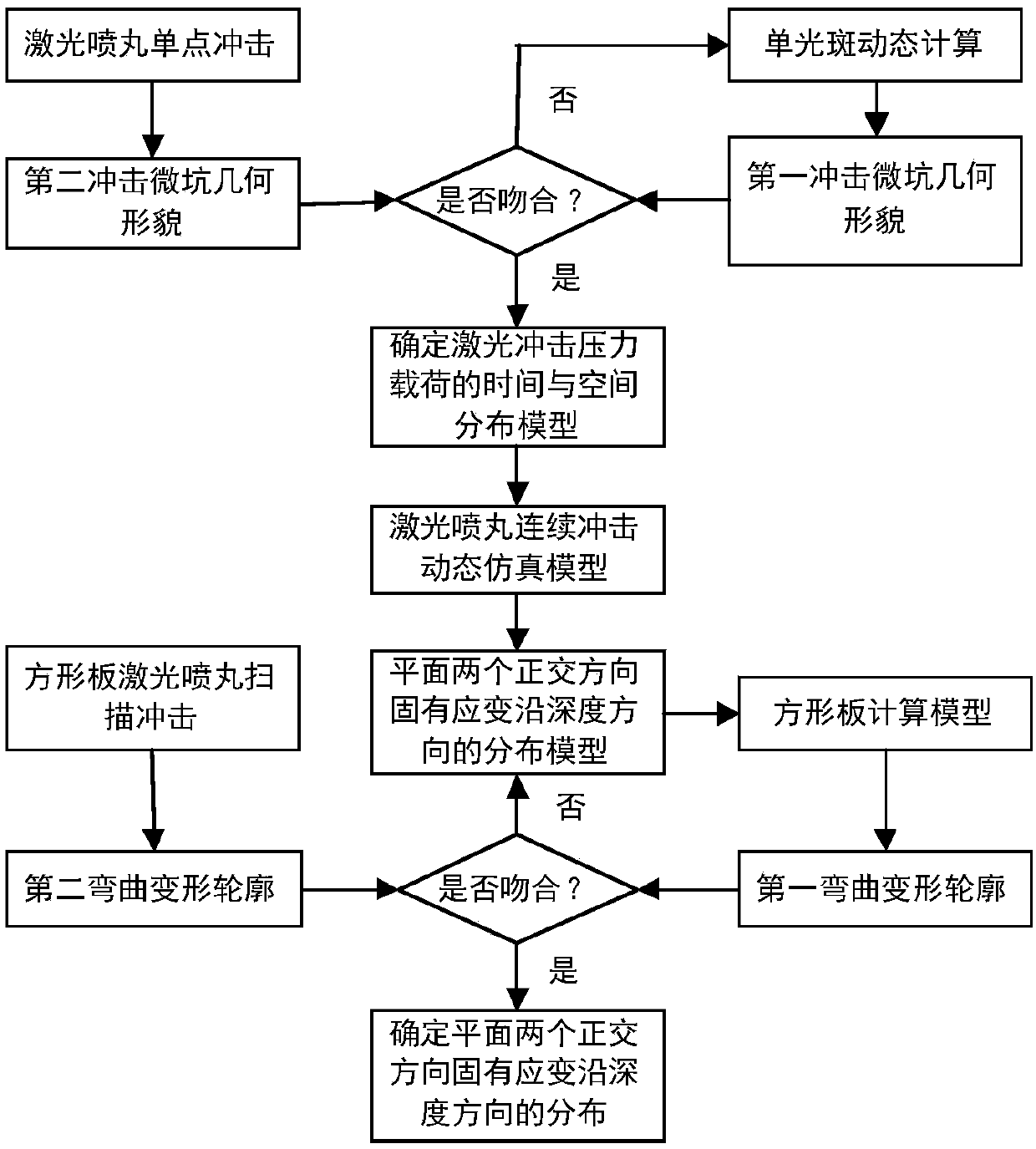
[0033] Such as figure 1 As shown, in this embodiment, the method for determining the inherent strain of laser peening based on the calculation model provided by the present invention includes the following steps:

[0034] Model simulation steps: perform laser peening single-point impact on the material, determine the time and space distribution model of laser impact pressure load and establish a dynamic simulation model of laser peening continuous impact, and extract the inherent strain in two orthogona...


PUM


Abstract

The invention provides a calculation model-based method for determining inherent strains of laser peening. The method comprises the steps of performing laser peening single-point shock on a material,determining a time and space distribution model of laser shock pressure loads, building a laser peening continuous shock dynamic simulation model according to the time and space distribution model, extracting a distribution model of the inherent strains in two orthogonal directions of a plane in a depth direction, building a square plate calculation model according to the distribution model, and performing calculation to obtain first bending deformation contour data of the square plate calculation model; performing laser peening scanning shock on the same material, and performing measurement to obtain second bending deformation contour data; and comparing the first bending deformation contour data and the second bending deformation contour data, and correcting the distribution model of theinherent strains in the two orthogonal directions of the plane in the depth direction. The method provided by the invention has the characteristics of simplicity and convenience, accuracy and low cost; and the accuracy of obtaining the inherent strains can be improved.

Description

technical field [0001] The invention relates to the technical field of mechanical processing, in particular to a method for determining the intrinsic strain of laser shot peening based on a calculation model. Background technique [0002] Laser peening process is an emerging metal surface strengthening and plate forming technology. Compared with traditional mechanical shot peening, it has the outstanding characteristics of greater depth of plastic layer, stronger process controllability, and higher processing surface quality. Due to the above advantages, laser peening has broad application prospects in the engineering practice of aerospace and national defense, such as the aerodynamic shape forming of aircraft fuselage panels, the strengthening of aeroengine turbine blades, and the forming of launch vehicle fuel storage tanks. . [0003] The basic principle of laser peening is to cause plastic strain on the surface of the plate through laser shock, thereby introducing resid...

Claims


Application Information

Patent Timeline
IPC IPC(8): G06F17/50
CPCG06F30/17G06F30/20G06F2119/06
Inventor 胡永祥解宇飞姚振强
Owner SHANGHAI JIAO TONG UNIV
Learn More