Binocular vision based object location grabbing method for mechanical arm

A binocular vision, target positioning technology, applied in image data processing, instruments, calculations, etc., can solve the problems of control system and servo operation not working normally, grasping and other problems, to meet time requirements, less calculation, simple method Effect

Active Publication Date: 2018-03-06
DALIAN UNIV OF TECH
View PDF5 Cites 64 Cited by
  • Summary
  • Abstract
  • Description
  • Claims
  • Application Information

AI Technical Summary

Problems solved by technology

This method overcomes the problems that the existing robotic arm system cannot autonomously grasp according to the complex field environm

Method used


Image

  • Binocular vision based object location grabbing method for mechanical arm
  • Binocular vision based object location grabbing method for mechanical arm
  • Binocular vision based object location grabbing method for mechanical arm

Examples


Embodiment Construction

[0051] The present invention will be further described below in conjunction with accompanying drawing.

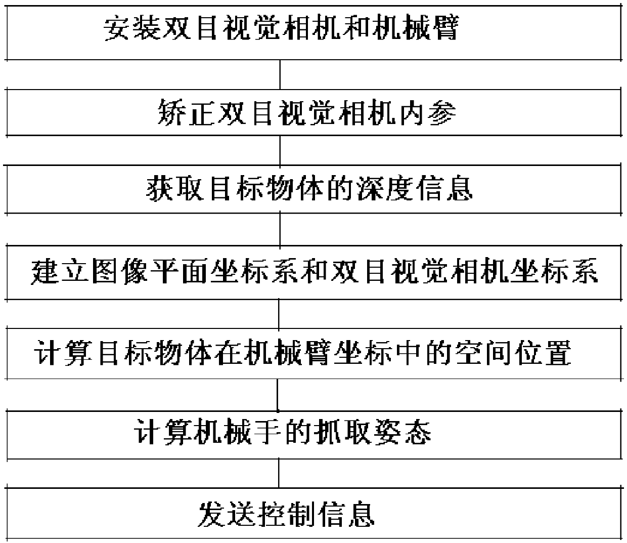
[0052] Such as figure 1 As shown, a binocular vision-based robotic arm target positioning and grasping method includes the following steps:

[0053] Step 1. Install the binocular vision camera and the robotic arm, where the binocular vision camera is placed horizontally, and ensure that the binocular vision camera and the base of the robotic arm are on the same level, and shoot objects horizontally. The recognition area is within the working radius of the robotic arm. Requirements The distance between the position of the binocular vision camera and the recognition area is 0.8-20.0 meters and ensure that the recognition area is not blocked;

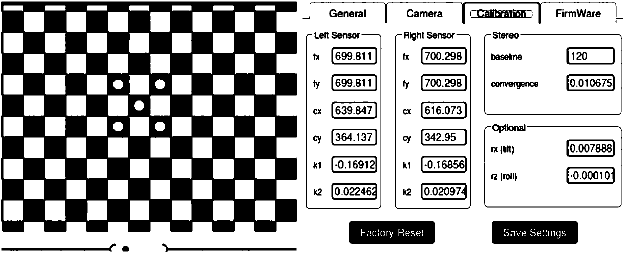
[0054] Step 2. Correct the internal parameters of the binocular vision camera. The internal parameters of the binocular vision camera are parameters related to the characteristics of the binocular vision camera itself. This can determi...


PUM


Abstract

The invention relates to the field of mechanical arms and computer vision technology. The binocular vision based object location grabbing method for a mechanical arm includes steps of 1, mounting a binocular vision camera and a mechanical arm; 2, correcting inner parameters of the binocular vision camera; 3, obtaining depth information of a target object; 4, establishing an image planar coordinatesystem and a binocular vision camera coordinate system; 5, calculating the spatial position of the target object in the mechanical arm coordinate system; 6, calculating the grabbing gesture of the mechanical arm; 7, sending control information. Compared with the prior art, the method has advantages that 1, time requirements for real time grabbing can be met since an object recognition method is simple and the calculation load is comparatively low; 2, a problem of operation failure, which occurs when fine difference exists between the gesture of the target object and an ideal gesture, of a mechanism system adopting a traditional demonstration system is avoided.

Description

technical field [0001] The invention relates to a binocular vision-based target positioning and grasping method of a mechanical arm, which belongs to the technical field of mechanical arms and computer vision. Background technique [0002] With the birth of the world's first industrial robot in the late 1850s, people's dream of using robots to replace human heavy labor has never stopped. Among them, the autonomous grasping ability has become the standard for the level of robot intelligence, while robot vision has become the main way for robots to obtain external information with low cost and high reliability. [0003] In modern industrial production, the grasping of the robotic arm mostly uses the teaching system, but the industrial environment is complex, and there may be a large error between the actual grasping target pose and the ideal pose, which makes the teaching system unable to work normally. In response to this problem, there is already an Eye-in-Hand model on the...

Claims


Application Information

Patent Timeline
IPC IPC(8): G06T7/80G06T7/90G06T7/136
CPCG06T7/136G06T7/85G06T7/90
Inventor 王东贾未连捷王振宇王伟
Owner DALIAN UNIV OF TECH
Why Eureka
Try Eureka