Light emitting diode with two-segment pins

A light-emitting diode, two-stage technology, applied in the direction of electrical components, circuits, semiconductor devices, etc., can solve the problems of easy deformation and misalignment of the PIN pins of LED lights, and achieve side-emitting effects, simple installation, and fast assembly Effect

Pending Publication Date: 2018-03-06
苏州市悠文电子有限公司
View PDF8 Cites 1 Cited by
  • Summary
  • Abstract
  • Description
  • Claims
  • Application Information

AI Technical Summary

Problems solved by technology

[0005] The beneficial effect of the light-emitting diode with two-stage PIN pins of the present invention is that the pins are set as two-stage branch pins, and when the pins are assembled, the first branch pin connected to the LED lamp is first inserted into the horizontal straight through hole Then insert the second branch pin with a set length into the vertical straight through hole, and finally connect the two through the conductive shrapnel; there is no need to use a bending machine or a shearing machine to bend and cut the PIN pin in and out , solves the problem that the PIN pin of the LED lamp is easily deformed and displaced in the traditional process, and then affects the effect of side lighting; it has the advantages of simple installation, reducing the deformation and deviation of the PIN pin, ensuring the effect of side lighting, fast assembly, and low cost.

Method used


Image

  • Light emitting diode with two-segment pins
  • Light emitting diode with two-segment pins
  • Light emitting diode with two-segment pins

Examples


Embodiment 1

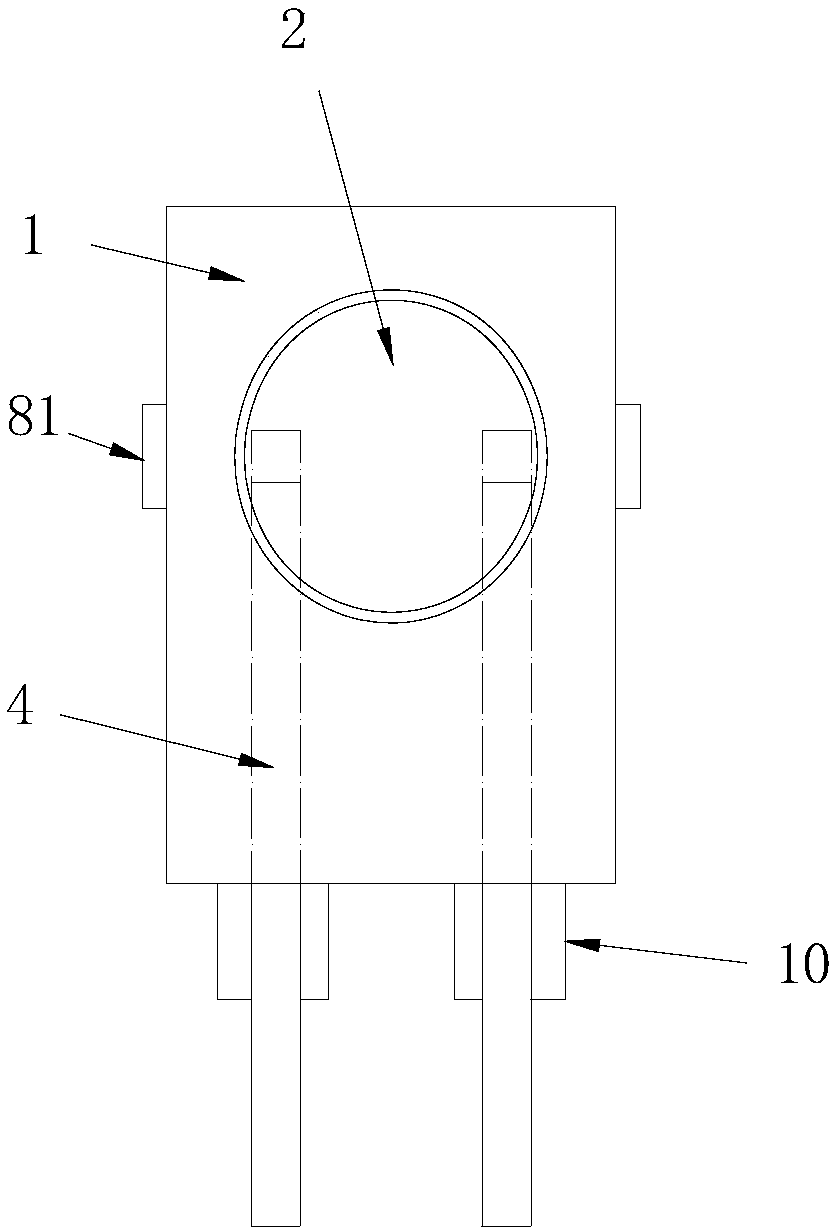
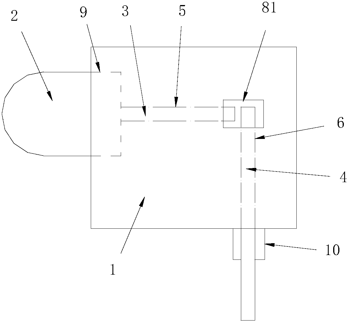
[0020] Embodiment one, see appendix Figure 1-2 As shown, a light-emitting diode with two-stage PIN pins in this embodiment includes a lamp housing 1, an LED lamp 2, and two pins, both pins are arranged on the LED lamp 2, and the pins pass through The lamp housing 1 is provided with horizontal straight through holes 5 and vertical straight through holes 6 which are perpendicular to each other. Each pin is composed of two branch pins, namely the first branch pin 3 and the second branch pin. Two branch pins 4, one end of the first branch pin 3 is connected to the LED lamp 2, the other end of the first branch pin 3 penetrates the horizontal straight through hole 5, and the lamp housing 1 is provided with an LED lamp accommodating groove 9, The base of the LED lamp 2 is installed in the LED lamp accommodating groove 9; the second branch pin 4 penetrates the vertical straight through hole 6, and one end of the two branch pins located in the lamp housing 1 is connected by a conducti...

Embodiment 2

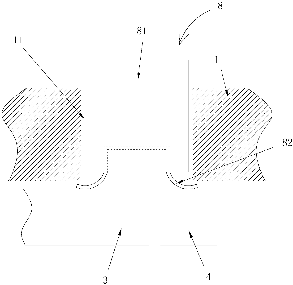
[0022] Embodiment two, see appendix Figure 4 , 5 As shown, the difference between the conductive elastic sheet in this embodiment and the first embodiment is that the conductive elastic sheet adopts a plug-in conductive elastic sheet 7, and the plug-in conductive elastic sheet 7 includes a first casing 71 and a first conductive elastic sheet 72. The first casing 71 Built in the lamp housing 1, the first shell 71 is provided with a conductive shrapnel groove 73, the two ends of the first conductive shrapnel 72 are set in the conductive shrapnel groove 73, and the middle part of the first conductive shrapnel 72 has an arched part 74, arched The raised portion 74 protrudes from the first housing 71 and presses one end of the two branch pins located in the lamp housing 1 by the elasticity of the first conductive elastic piece 72 . The arched part 74 and the branch pin are fixed by the structure of the groove 75 and the protrusion 76. The groove 75 in this embodiment is arranged ...


PUM


Abstract

The invention discloses a light emitting diode with two-segment pins. The light emitting diode comprises a lamp housing, an LED lamp and two pins, the two pins are both arranged on the LED lamp, the pins penetrate through the lamp housing, a transverse linear through hole and a vertical linear through hole vertical to each other are arranged in the lamp housing, each pin is formed by two segmentsof branch pins including a first branch pin and a second branch pin, one end of the first branch pin is connected with the LED lamp, the other end of the first branch pin penetrates through the transverse linear through hole, the second branch pin penetrates through the vertical linear through hole, and one ends of the two segments of branch pins located in the lamp housing are connected through conductive spring sheets. According to the light emitting diode, the pins are set as two segments of branch pins which are finally connected through the conductive spring sheets, bending and shearing of the pins by a bending machine and a shearing machine can be avoided, the installation is simple, the deformation and the deviation of the pins are reduced, the side light-emitting effect is guaranteed, the assembling is rapid, and the cost is low.

Description

technical field [0001] The invention relates to the field of light-emitting diodes, in particular to a light-emitting diode with two-stage PIN pins. Background technique [0002] Side LED means that the LED light on the side of the lamp housing emits light, and the bottom is soldered to the circuit board through the patch-type pad or the plug-in PIN pin. Once the circuit board is powered on, the LED light on the side of the lamp housing will emit light, and then realize the side lighting function. Because it is side-emitting, the PIN pin that is finally connected to the LED light is in a right-angle shape. At present, the process of installing and connecting the PIN pins connected with LED lamps in the lamp housing is: first insert the traditional lamp LED into the lamp housing, and then use a bending machine to bend the PIN pins by 90°. Cut the PIN pin protruding from the lamp housing to a suitable length for welding, and finally complete the work. In the process of bend...

Claims


Application Information

Patent Timeline
Patent Type & Authority Applications(China)
IPC IPC(8): H01L33/48H01L33/62
CPCH01L33/483H01L33/62
Inventor 王友平
Owner 苏州市悠文电子有限公司
Why Eureka
Try Eureka