
Automatic drying oven used for production of printed circuit board assembly

A technology for printed circuit boards and ovens, which is applied to printed circuits, printed circuit manufacturing, and printed circuit assembly of electrical components. It can solve the problems of easily damaged circuit boards, difficult temperature control, and waste of resources. simple effect

Inactive Publication Date: 2018-03-06
ANHUI SHENZE ELECTRONICS TECH
View PDF6 Cites 6 Cited by
  • Summary
  • Abstract
  • Description
  • Claims
  • Application Information

AI Technical Summary

Problems solved by technology

Apply solder paste on the circuit board, paste chips or other components and place it in an oven for heating, so that the solder paste is melted and welded. The existing automatic oven for the production of printed circuit board components is not easy to control the temperature. During the heating process, the heating temperature cannot be directly displayed, and there is no temperature alarm function. If the temperature is too high, the circuit board will be easily damaged. In addition, when there is no circuit board on the conveying mechanism, the heating device cannot be turned off in time, resulting in waste of resources.

Method used


Image

  • Automatic drying oven used for production of printed circuit board assembly
  • Automatic drying oven used for production of printed circuit board assembly
  • Automatic drying oven used for production of printed circuit board assembly

Examples


Embodiment Construction

[0019] The following will clearly and completely describe the technical solutions in the embodiments of the present invention with reference to the accompanying drawings in the embodiments of the present invention. Obviously, the described embodiments are only some, not all, embodiments of the present invention. Based on the embodiments of the present invention, all other embodiments obtained by persons of ordinary skill in the art without making creative efforts belong to the protection scope of the present invention.

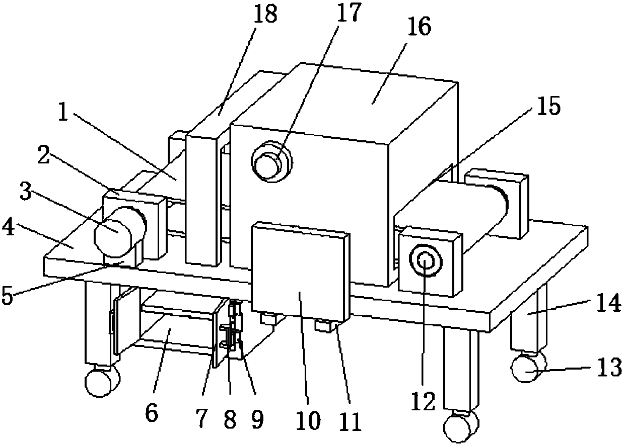
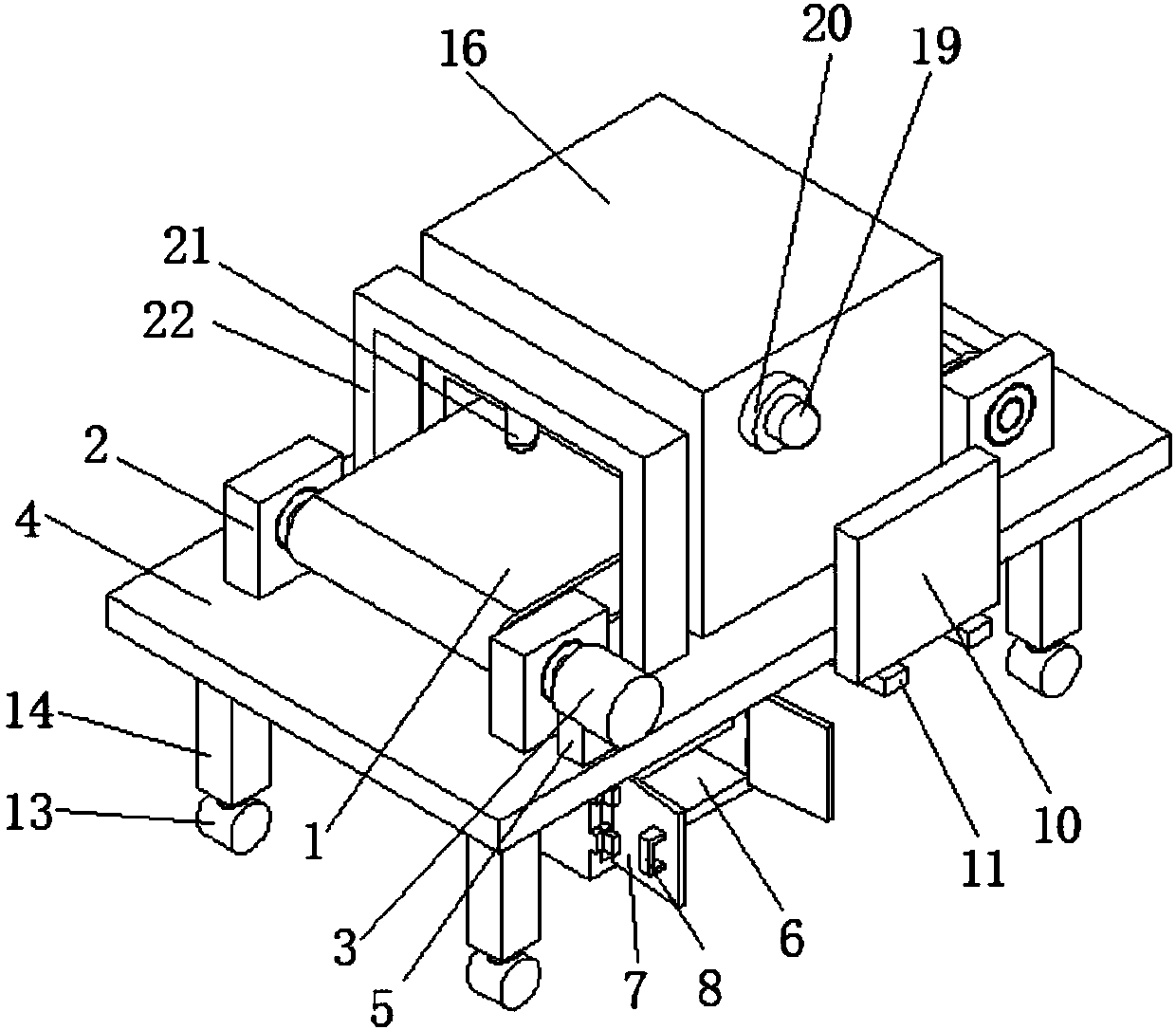
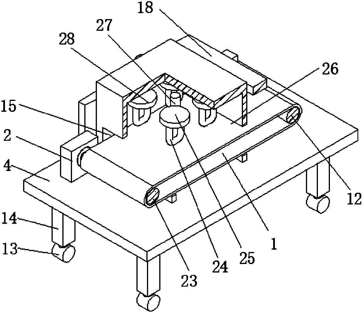
[0020] see Figure 1-3 , the present invention provides a technical solution: an automatic oven for the production of printed circuit board assemblies, including a bottom plate 4, the lower surface of the bottom plate 4 is provided with support legs 14, the number of support legs 14 is four and arranged at equal intervals, and supports The bottom end of leg 14 is provided with roller 13, by supporting the roller 13 under leg 14, device can be moved, is conveni...


PUM


Abstract

The invention discloses an automatic drying oven used for production of a printed circuit board assembly. The automatic drying oven comprises a bottom plate; a supporting plate is arranged in the middle part of the front end of the bottom plate; a PLC controller is arranged on the upper surface of the supporting plate; the input end of the PLC controller is electrically connected with the output end of an external power supply; four bearing pedestals are arranged on the upper surface of the bottom plate; a driving roller is arranged between two bearing pedestals in a sleeving manner while a driven roller is arranged between the other two bearing pedestals in a sleeving manner; the outer surface of the driving roller and the outer surface of the driven roller are sleeved with a conveyor belt; a fixed base is arranged on the left side of the front end of the bottom plate; a motor is arranged on the upper surface of the fixed base; the input end of the motor is electrically connected withthe output end of the PLC controller; and the motor output shaft is connected with the driving roller through a coupling. The automatic drying oven used for production of the printed circuit board assembly is simple in structure, convenient to use, movable to be butt jointed with other equipment conveniently, and capable of accurately controlling the heating temperature, giving out an alarm whenthe temperature is overhigh, realizing automatic start and stop, and saving energy.

Description

technical field [0001] The invention relates to the technical field of printed circuit board assembly production, in particular to an automatic oven for the production of printed circuit board assemblies. Background technique [0002] When the circuit board is printed and produced, it is necessary to install circuit modules on it, such as chips, which need to be pasted with solder paste, and then the circuit board is heated according to a specific reflow temperature curve to melt the solder paste, and its alloy components are cooled and solidified. The metallurgical connection is achieved by forming solder joints between the device and the printed circuit board. Apply solder paste on the circuit board, paste chips or other components and place it in an oven for heating, so that the solder paste is melted and welded. The existing automatic oven for the production of printed circuit board components is not easy to control the temperature. During the heating process, the heati...

Claims


Application Information

Patent Timeline
IPC IPC(8): H05K3/34
CPCH05K3/3494
Inventor 赵守江胡洪波张琳张雷姜广彪展春雷赵守波张岐赵乾龙赵小龙
Owner ANHUI SHENZE ELECTRONICS TECH
Learn More