Damping buffer device

A buffer device and buffer rod technology, which is applied in the direction of shock absorbers, springs/shock absorbers, shock absorbers, etc., can solve the problems of large shear force of connecting bolts, shortened service life, poor sealing effect of buffer parts, etc., to achieve Good shock absorption and cushioning effect, prolong service life and increase contact area

Inactive Publication Date: 2018-03-09
朱丽辉
View PDF0 Cites 4 Cited by
  • Summary
  • Abstract
  • Description
  • Claims
  • Application Information

AI Technical Summary

Problems solved by technology

[0002] The collision head boss on the existing shock absorbing and buffering device is round, and the groove on the guide column is also round. When the collision head and the guide column are subjected to a large external force, they will not close tightly. The relative rotation will cause the connecting bolts to be subjected to a large shear force, causing the bolts to break, requiring production to be stopped for maintenance, and production to be delayed
In addition, the guide copper sleeve of the device is in contact with the guide column and has a small area, which cannot completely fix the running track of the guide column, and the guide copper sleeve is easy to wear, resulting in shortened service life
And the sealing effect of its cushioning part is poor, and the shock absorption and cushioning effects are not ideal

Method used


Image

  • Damping buffer device

Examples


Embodiment Construction

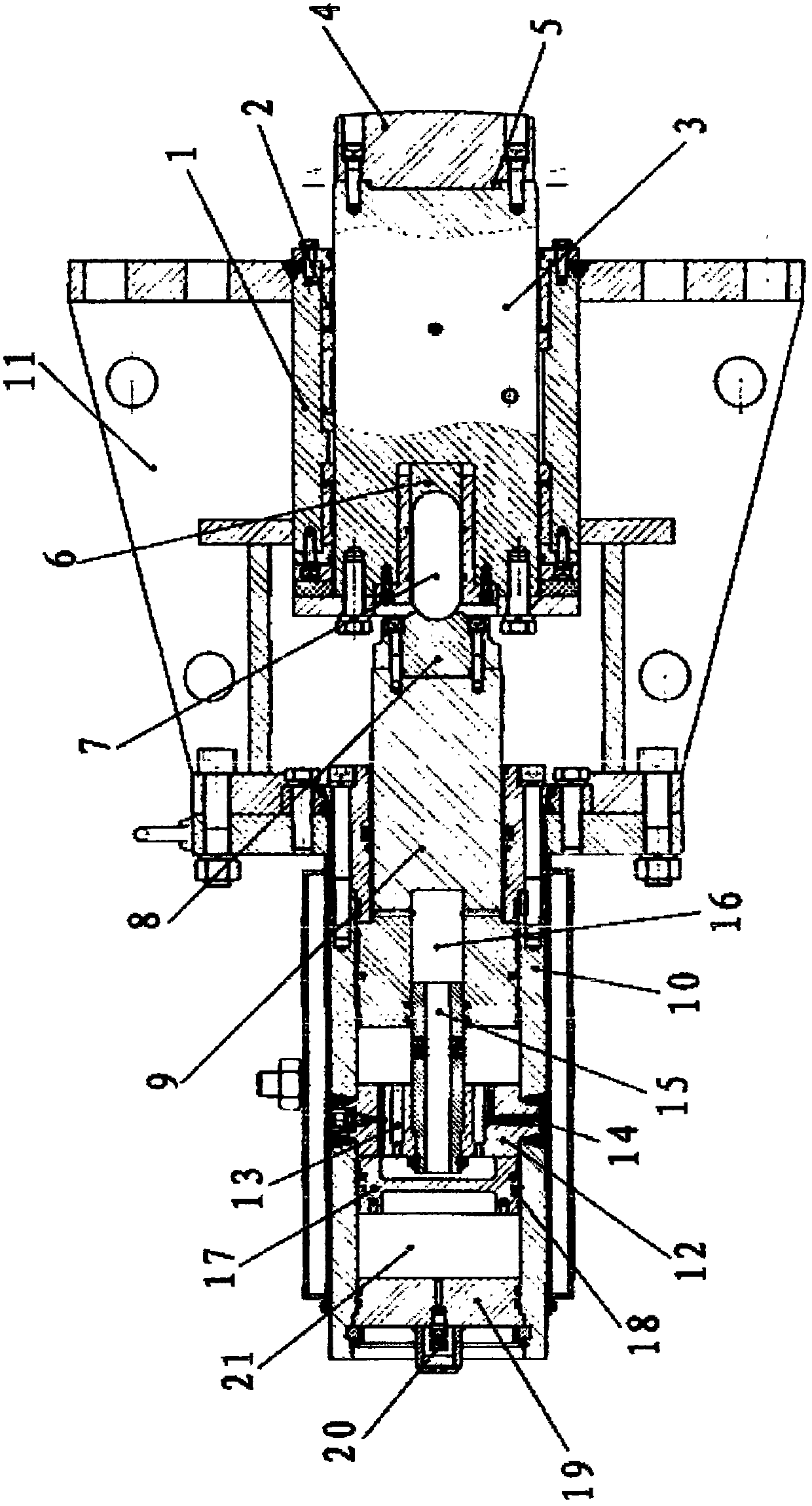
[0007] Referring to Figure 1, it includes a guide cylinder 1, three guide copper sleeves 2 are fixed on the inner wall of the guide cylinder, the guide column 3 is placed in the three guide copper sleeves, the front end of the guide column has a square groove, and the collision head 4 There is a square boss 5, the square boss is placed in the square groove on the guide column, the collision head and the guide column are connected together by bolts, the rear end of the guide column has a groove for the ball head rod, and the ball head rod seat 6 is placed on the At the bottom of the groove of the ball stud, the front end of the ball stud 7 is in contact with the ball stud seat, the rear end of the ball stud protrudes from the guide column, and there is a bumper 8 behind the ball stud, and the front end of the bumper There is a groove, the rear end of the ball-end rod is pushed in the groove of the bump block, and there is a piston rod 9 behind the bump block, and the bump block ...


PUM


Abstract

The shock absorbing and buffering device relates to a device capable of playing the role of shock absorbing and buffering. The utility model is mainly designed to solve the problems of unsatisfactory damping and buffering effects of existing shock absorbing buffer devices. It includes a guide cylinder, the guide post is placed in the guide copper sleeve, the square boss of the collision head is placed in the square groove of the guide post, the ball head rod seat is placed in the ball head rod groove of the guide post, and the ball head rod The front end is in contact with the ball-end rod seat, the rear end of the ball-end rod is pushed against the groove of the bumper fixed on the piston rod, the cylinder and the guide cylinder are connected through the connecting frame, and the buffer rod fixing plate in the cylinder has a The oil chamber channel and exhaust nozzle, the buffer rod is placed in the groove of the piston rod, the buffer rod is fixed on the buffer rod fixing plate, the piston is placed in the cylinder and is in contact with the inner wall of the cylinder, and there is an inflatable valve plate at the rear end of the cylinder. There is an inflation nozzle on the inflation valve plate, and the space between the inflation valve plate and the piston is an air chamber. The advantage is that the shock absorption and cushioning effects are good.

Description

Technical field: [0001] The invention relates to a device that can play the role of shock absorption and buffering. Background technique: [0002] The collision head boss on the existing shock absorbing and buffering device is round, and the groove on the guide column is also round. When the collision head and the guide column are subjected to a large external force, they will not close tightly. The relative rotation causes the connecting bolts to be subjected to a large shear force, causing the bolts to break, requiring production to be stopped for maintenance, and production to be delayed. In addition, the guide copper sleeve of the device is in contact with the guide column and has a small area, which cannot completely fix the running track of the guide column, and the guide copper sleeve is easy to wear, resulting in shortened service life. And the sealing effect of its cushioning part is poor, and the shock absorption and cushioning effects are also unsatisfactory. I...

Claims


Application Information

Patent Timeline
IPC IPC(8): F16B41/00F16F9/18F16F9/32
CPCF16B41/00F16F9/18F16F9/32
Inventor 朱丽辉
Owner 朱丽辉
Why Eureka
Try Eureka