Glare-proof light emitting device

A light-emitting device and anti-glare technology, applied in the field of lighting, can solve the problems of limited irradiation distance, large volume and heavy weight of the reflector, and achieve the effect of small lens size

Pending Publication Date: 2018-03-09
GUANGZHOU DASEN LIGHTING ELECTRONICS
View PDF9 Cites 0 Cited by
  • Summary
  • Abstract
  • Description
  • Claims
  • Application Information

AI Technical Summary

Problems solved by technology

[0004] For this reason, the technical problem to be solved by the present invention is that the existing COB light-emitting devices above 100W have the shortcomings of large reflectors that cannot polarize light, heavy weight, limited irradiation distance, low light utilization rate, and easy glare. Anti-glare lighting device with small size, light weight, long irradiation distance and concentrated light

Method used


Image

  • Glare-proof light emitting device
  • Glare-proof light emitting device

Examples


Embodiment

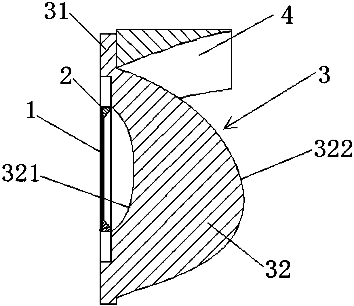
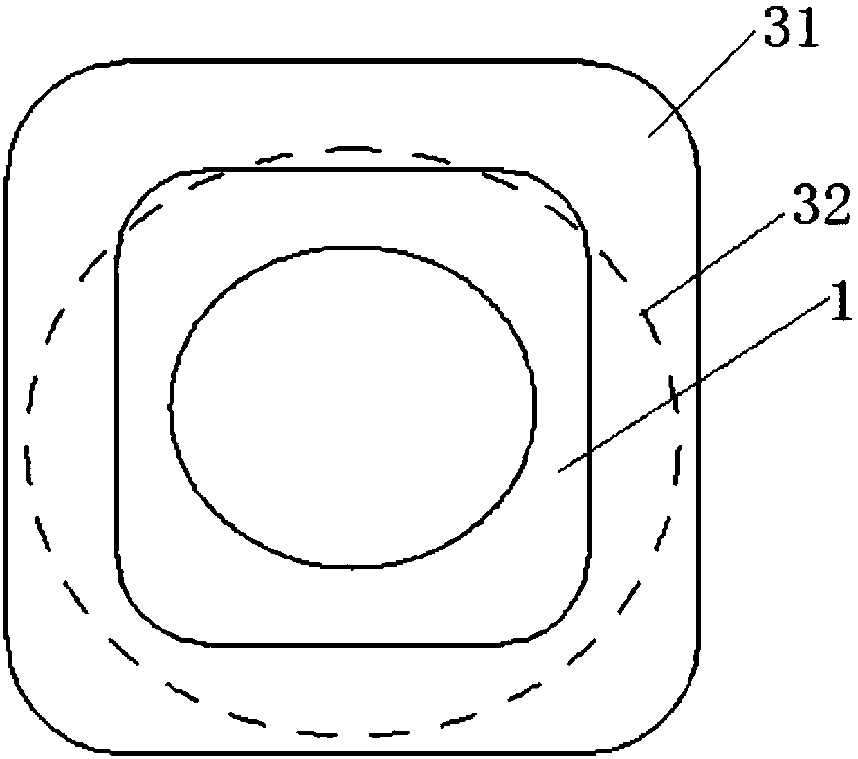
[0025] This embodiment provides an anti-glare lighting device, such as Figure 1-2 As shown, the light emitting device includes a light source 1, a reflective washer 2, a polarizing lens 3 and a specular reflector 4 connected in sequence, wherein the light source 1 is a COB light source, the reflective washer 2 is a plastic washer, and the mirror surface The reflector 4 can be made of plastic or optical glass, and its surface is coated with a layer of anti-corrosion and high reflectivity. Most of the light emitted by the light source 1 enters the polarizing lens 3. The large-angle light at the edge of the light source 1 enters the polarizing lens 3 after being reflected by the reflective gasket 2. The polarizing lens 3 collects the light and distributes the angle of the refracted light. The light emitted by the polarizing lens 3 is reflected by the inner surface of the mirror reflection component 4 to make the angular direction of the light consistent with the angular directio...


PUM


Abstract

The invention discloses a glare-proof light emitting device. The glare-proof light emitting device comprises a light source, a reflective washer, a polarizing lens and a mirror reflection assembly which are connected in sequence. The reflective washer is arranged at the exterior of a light emitting element of the light source in a sleeving mode. The polarizing lens is arranged on the light outletside of the light source. The mirror reflection assembly is arranged on the light outlet surface side of the polarizing lens. The mirror reflection assembly is arranged on one side surface of the light source. Most of light rays emitted by the light source enter the polarizing lens, large-angle light rays are reflected by the reflective washer and then enter the polarizing lens, the light rays arecollected by the polarizing lens, and angles of the refracted light rays are distributed; and after the light rays emitted by the polarizing lens are reflected by the inner surface of the mirror reflection assembly, the angle direction of the light rays is the same with the angle direction of the polarizing lens, so that the large-angle light rays are controlled and utilized, and the situation ofglaring is reduced.

Description

technical field [0001] The invention belongs to the technical field of illumination, and in particular relates to an anti-glare light emitting device. Background technique [0002] LED light source is the focus of the light source market in the 21st century. As a new energy-saving, environmentally friendly and green light source product, it has become the fourth-generation light source and will be the development trend of the future light source. LED light sources have the advantages of long life, high luminous efficiency, strong stability, no mercury, no radiation, low energy consumption, etc., and have a variety of packaging methods. Among them, the COB (Chip On Board) package can directly package multiple chips on the metal-based printed circuit board, and directly dissipate heat through the substrate. Compared with the traditional SMT chip package and high-power package, it not only reduces the manufacturing process of the bracket and The cost also has the advantage of ...

Claims


Application Information

Patent Timeline
Patent Type & Authority Applications(China)
IPC IPC(8): F21K9/20F21K9/68F21K9/69F21V7/00F21V5/04F21Y115/10
CPCF21V5/04F21V7/00
Inventor 许法卿
Owner GUANGZHOU DASEN LIGHTING ELECTRONICS
Why Eureka
Try Eureka