Aircraft-based traffic monitoring system and monitoring method

A monitoring system and aircraft technology, applied in the field of aerial photography, can solve the problem that traffic monitoring can only be monitored at fixed points

Pending Publication Date: 2018-03-09
CHENGDU UNIV
View PDF5 Cites 4 Cited by
  • Summary
  • Abstract
  • Description
  • Claims
  • Application Information

AI Technical Summary

Problems solved by technology

[0004] The purpose of the present invention is to provide a traffic monitoring system based on aircraft, which solves the problem that existing traffic monitoring can only be monitored at fixed points, and at the same time, the flight stability of the aircraft described in the present invention is good

Method used


Image

  • Aircraft-based traffic monitoring system and monitoring method

Examples


Embodiment 1

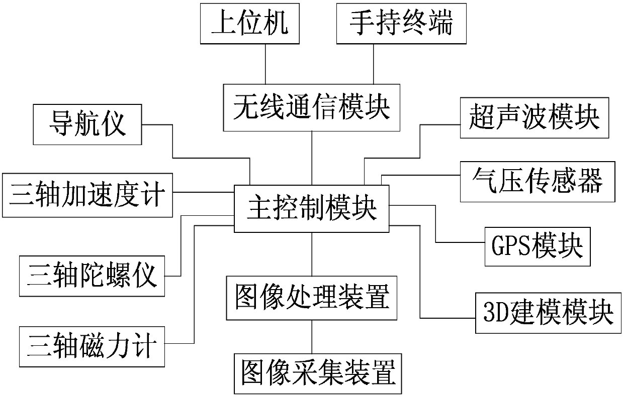
[0044] Such as figure 1 As shown, the aircraft-based traffic monitoring system includes an aircraft, and the aircraft is provided with a navigator, a main control module, a wireless communication module, an ultrasonic module, an air pressure sensor, an image processing device and an image acquisition device,

[0045] The navigator is used to realize the flight of the aircraft on the set route, and the navigator transmits the navigation signal to the main control module, and then transmits it to the remote terminal through the wireless communication module;

[0046] The image acquisition device is used to collect pictures or video signals on the path of the aircraft, and transmit the signal to the image processing device, and the image acquisition device is a high-definition camera or a high-definition camera;

[0047] The image processing device processes the picture or video signal and transmits it to the main control module, and the main control module is an MCU processor; ...

Embodiment 2

[0053] Such as figure 1 As shown, this embodiment is based on Embodiment 1, and the high-definition camera or the high-definition camera is connected to the aircraft through a pan / tilt.

[0054] Example 2:

[0055] Such as figure 1 As shown, the present embodiment is based on embodiment 1 or embodiment 2, and the main control module is connected with a three-axis accelerometer, a three-axis gyroscope and a three-axis magnetometer in communication, and the three-axis accelerometer, a three-axis gyroscope and a three-axis The axis magnetometer is set on the aircraft; the aircraft is also provided with a GPS module or a Beidou system that communicates with the main control module; and the aircraft is also provided with a 3D modeling module that communicates with the main control module.

[0056] A monitoring method based on a traffic monitoring system, comprising the following steps:

[0057] 1) Through the navigation of the navigator, the aircraft can fly back and forth along...


PUM


Abstract

The invention discloses an aircraft-based traffic monitoring system and monitoring method. The monitoring system comprises an aircraft. A navigator, a master control module, a wireless communication module, an ultrasonic module, an air pressure sensor, an image processing device and an image collecting device are arranged on the aircraft; the image collecting device is used for collecting picturesor video signals on a path of the aircraft and transferring the signals to the image processing device; the image processing device is used for processing the pictures or video signals and then transferring the same to the master control module; the master control module is used for receiving the processed pictures or video signals and transferring the same to a remote terminal by means of the wireless communication module; the air pressure sensor and the ultrasonic module separately collect air pressure in the environment of the aircraft and distance from the aircraft to an obstacle and transfers the same to the master control module and then transfers the same to the remote terminal through the wireless communication module. The system provided by the invention solves the problem that existing traffic can be only monitored at fixed points, and meanwhile, the flying stability of the aircraft is good.

Description

technical field [0001] The invention relates to the technical field of aerial photography, in particular to an aircraft-based traffic monitoring system and a monitoring method. Background technique [0002] With the development of communication technology, the existing traffic monitoring mainly relies on electronic eyes for capturing. The electronic eye capture system mainly includes the electronic eye set at each capture point, the image processing module, the wireless communication module and the remote monitoring center. The module is transmitted to the remote monitoring center for storage and filing, and the remote monitoring center conducts analysis and transmits the analysis results to the owner of the vehicle involved in the accident. [0003] Although the electronic eye capture system can monitor traffic accidents and violations very well, it can only monitor at fixed points. It cannot monitor the position where the electronic eye is not installed. collection. Co...

Claims


Application Information

Patent Timeline
Patent Type & Authority Applications(China)
IPC IPC(8): G08G1/04B64C39/02
CPCG08G1/04B64C39/024B64U2101/30B64U2201/10B64U2201/20
Inventor 雷霖葛一楠赵永鑫伍星豪范烊
Owner CHENGDU UNIV
Why Eureka
Try Eureka