
Array substrate and preparation method thereof

An array substrate and substrate technology, applied in the field of array substrate and its preparation, can solve the problems affecting the characteristics of TFT, the black screen of the display panel, etc., and achieve the effect of improving reliability

Active Publication Date: 2018-03-09
BOE TECH GRP CO LTD
View PDF5 Cites 17 Cited by
  • Summary
  • Abstract
  • Description
  • Claims
  • Application Information

AI Technical Summary

Problems solved by technology

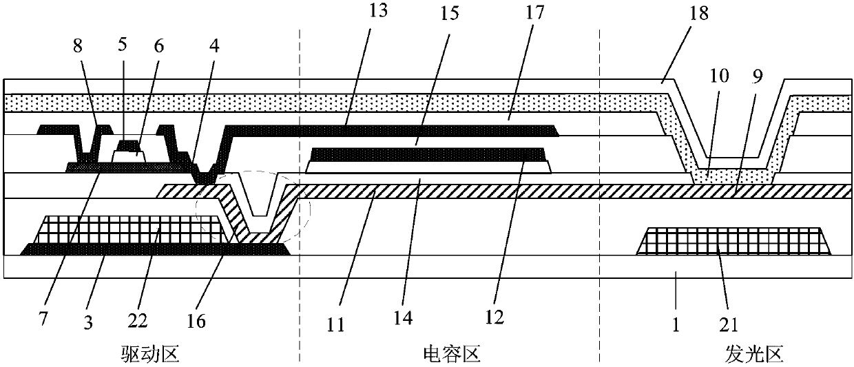
[0003] The inventors found that although the light-shielding layer can avoid the influence of external light (light from outside the display panel) on the TFT, since the TFT is closer to the substrate than the OLED, that is, the position of the OLED is much higher than that of the TFT, the light emitted by the OLED After the light diffuses in the display panel, it will irradiate the TFT area, which will affect the characteristics of the TFT and cause the black screen to appear white when the display panel is displayed.

Method used


Image

  • Array substrate and preparation method thereof

Examples


Embodiment 1

[0027] Such as figure 1 As shown, this embodiment provides an organic light emitting diode (OLED) array substrate, which includes a base 1, the base 1 is divided into a plurality of sub-pixels of different colors, each sub-pixel includes a driving region, a capacitor region and a light-emitting region, each At least one thin-film transistor (TFT) is arranged in the driving region; an organic light-emitting diode is arranged in the light-emitting region, and a first color filter structure 21 corresponding to the color of the sub-pixel where the light-emitting region is located is arranged below the organic light-emitting diode. In particular, the thin-film transistor A second color filter structure 22 is arranged below, and the second color filter structure 22 is arranged on the same layer as the first color filter structure 21 of at least one color.

[0028] Among them, up and down refer to the direction, specifically, such as figure 1 As shown, all the structures of the arra...

Embodiment 2

[0050] This embodiment provides a method for preparing an array substrate, which is used to prepare the array substrate provided in Embodiment 1. The preparation method includes:

[0051] Step 1. Using a patterning process on the base corresponding to the thin film transistor and the organic light-emitting diode in the sub-pixel of one color, respectively form the graphics of the second color filter structure and the first color filter structure.

[0052] Step 2, forming organic light emitting diodes and thin film transistors on the substrate after the above steps.

[0053] In the array substrate prepared by the preparation method provided in this embodiment, a first color filter structure is provided below the organic light emitting diode, and a second color filter structure is provided below the thin film transistor. The position is elevated, shortening the distance between the thin film transistor and the organic light emitting diode in the longitudinal direction, thereby ...


PUM


Abstract

The invention provides an array substrate and a preparation method thereof, and belongs to the technical field of display. By means of the array substrate, the problem can be solved that as the feature of an existing thin film transistor is influenced by the light of an organic light emitting diode, reverse display of a black screen is caused. The array substrate comprises a substrate, the substrate is divided into multiple subpixels in different colors, each subpixel comprises a driving region, a capacitance region and a light emitting region, and at least one thin film transistor is arrangedin each driving region; organic light emitting diodes are arranged in each light emitting region, a first color film structure corresponding to the color of the subpixel where each light emitting region is located is arranged below the organic light emitting diodes, a second color film structure is arranged below the thin film transistors, and the second color film structure and the first color film structure in at least one color are arranged in the same layer.

Description

technical field [0001] The invention belongs to the field of display technology, and in particular relates to an array substrate and a preparation method thereof. Background technique [0002] In the prior art, in the preparation process of the bottom-emitting organic light-emitting diode (OLED) display panel, before preparing the thin-film transistor (TFT), a light-shielding layer is usually formed on the substrate at the position corresponding to the active layer to prevent light from being (TFT) characteristics. [0003] The inventor found that although the shading layer can avoid the influence of external light (light from outside the display panel) on the TFT, since the TFT is closer to the substrate than the OLED, that is, the position of the OLED is much higher than that of the TFT, the light emitted by the OLED After the light diffuses and propagates in the display panel, it will irradiate the TFT area, which will affect the characteristics of the TFT, resulting in ...

Claims


Application Information

Patent Timeline
Patent Type & Authority Applications(China)
IPC IPC(8): H01L27/32
CPCH10K59/12H10K59/121H10K59/1201
Inventor 宋振王国英
Owner BOE TECH GRP CO LTD
Learn More