Constant on-time (COT) control Buck converter multi-pulse trigger improvement device

A constant on-time, converter technology, used in output power conversion devices, control/regulation systems, DC power input conversion to DC power output, etc., can solve the problem of small size, instability and multi-pulse burst of ceramic capacitors and other problems, to achieve the effect of reducing inductor current ripple, eliminating pulse bursting phenomenon, and solving application limitations

Pending Publication Date: 2018-03-09
CHANGZHOU XINGYU AUTOMOTIVE LIGHTING SYST CO LTD
View PDF0 Cites 3 Cited by
  • Summary
  • Abstract
  • Description
  • Claims
  • Application Information

AI Technical Summary

Problems solved by technology

[0003] However, the current Buck converter device based on constant on-time control still has the following disadvantages: the Buck converter using COT control has extremely strict requirements on the output capacitor, and the type and capacitance of the output capacitor, especially the ESR of the output capacitor, have a great impact on the entire system. The control performance of the switching converter has a great influence. At present, the Buck converter device based on constant on-time control adopts low output capacitor ESR, and there is a multi-pulse bursting phenomenon, which is unstable.
The current constant on-time controlled Buck converter needs to have a large output capacitor ESR to achieve. Some portable devices or mobile terminals cannot accommodate large electrolytic capacitors. Ceramic capacitors are small in size, but the output capacitor ESR of ceramic capacitors Very small, almost negligible, the above shortcomings limit the integration and promotion of COT control circuits

Method used


Image

  • Constant on-time (COT) control Buck converter multi-pulse trigger improvement device
  • Constant on-time (COT) control Buck converter multi-pulse trigger improvement device
  • Constant on-time (COT) control Buck converter multi-pulse trigger improvement device

Examples


Embodiment Construction

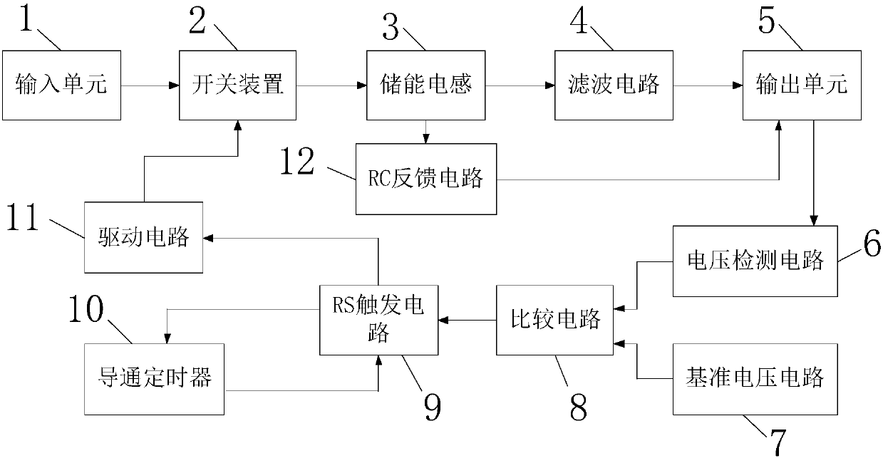
[0023] Such as figure 1 As shown, the present invention discloses a constant on-time control Buck converter multi-pulse burst improvement device, including a power circuit and a COT controller. The power circuit includes an input unit 1, a switching device 2, an energy storage inductor 3, a filter circuit 4, and Output unit 5, COT controller includes output voltage detection circuit 6, reference voltage circuit 7, comparison circuit 8, RS trigger circuit 9, on-timer 10, drive circuit 11 and RC feedback circuit 12, input unit 1 via switching device 2 Connected to the energy storage inductor 3, the energy storage inductor 3 is connected to the output unit 5 through the filter circuit 4, the output unit 5 is connected to the inverting input terminal of the comparison circuit 8 through the output voltage detection circuit 6, and the reference voltage circuit 7 is connected to the in-phase of the comparison circuit 8 Input terminal, the output terminal of the comparison circuit 8 is...


PUM


Abstract

The present invention relates to the technical field of switching power supplies, in particular to a device for improving multi-pulse bursting of Buck converters with constant on-time control, including a power circuit and a COT controller. The power circuit includes an input unit, a switching device, an energy storage inductor, a filter circuit and an output unit, the COT controller includes an output voltage detection circuit, a reference voltage circuit, a comparison circuit, an RS trigger circuit, an on-timer, a drive circuit and an RC feedback circuit. The present invention feeds back the current ripple signal of the energy storage inductance to the comparator, so that the output voltage of the multi-pulse burst improvement device of the constant on-time control Buck converter follows the current change of the energy storage inductance, and eliminates the problem of using a small output capacitor ESR The pulse bursting phenomenon makes the constant on-time control Buck converter work in a stable state, which solves the application limitations of the current COT control Buck converter.

Description

Technical field [0001] The present invention relates to the technical field of switching power supplies, in particular to a constant on-time control Buck converter multi-pulse burst improvement device. Background technique [0002] With the vigorous development of power electronic technology, the application field of switching power supply is becoming more and more extensive, especially the requirements of electronic equipment in the field of automotive electronics are getting higher and higher. The traditional pulse width modulation (PWM) control technology has the advantages of no steady-state error and fixed switching frequency, and has been widely used in switching power converters. However, PWM control usually requires an error amplifier and a corresponding compensation network, and the compensation network design is complicated. Constant on-time (COT) control is a control technique based on output voltage ripple, without error amplifier and compensation network, and variab...

Claims


Application Information

Patent Timeline
Patent Type & Authority Applications(China)
IPC IPC(8): H02M3/156H02M1/14
CPCH02M3/156H02M1/14
Inventor 董伟陈小龙王国云任康成董锋格
Owner CHANGZHOU XINGYU AUTOMOTIVE LIGHTING SYST CO LTD
Why Eureka
Try Eureka