Narrow-mouth baffle ring continuous mould stamping equipment

A technology for stamping equipment and retaining rings, which is applied in the field of continuous die stamping equipment for narrow-mouth retaining rings, can solve problems such as narrow waste connection parts, blocked product discharge, and narrow mouths, so as to achieve reasonable structural design, improve processing efficiency, and prevent The effect of secondary damage to the product

Pending Publication Date: 2018-03-13
ANHUI NINGGUO DONGBO FASTENER
View PDF7 Cites 6 Cited by
  • Summary
  • Abstract
  • Description
  • Claims
  • Application Information

AI Technical Summary

Problems solved by technology

However, if figure 1 As shown, the narrow mouth retaining ring is characterized by a narrow mouth and a small distance from the small hole to the edge, which cannot be punched and formed at one time.
Therefore, this mold adopts punching the small hole first, and then punching the overall outer circle to form, but due to the small position of the mouth and the narrow connection part of the waste material on the material belt, the product discharge is hindered, and automatic unloading cannot be realized

Method used


Image

  • Narrow-mouth baffle ring continuous mould stamping equipment
  • Narrow-mouth baffle ring continuous mould stamping equipment
  • Narrow-mouth baffle ring continuous mould stamping equipment

Examples


Embodiment Construction

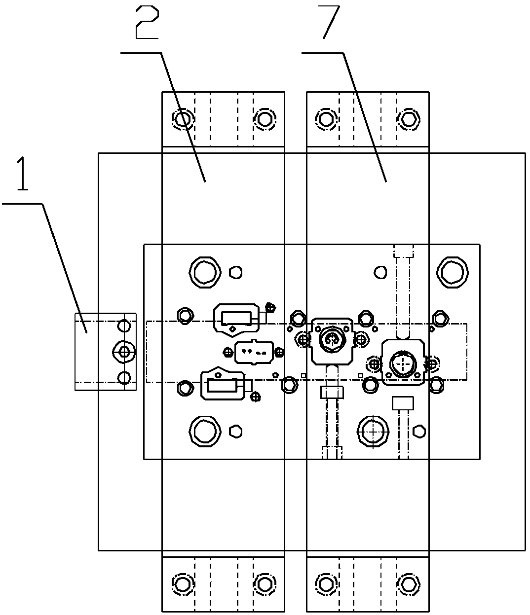
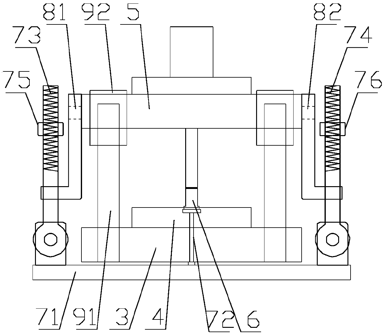
[0019] Such as Figures 1 to 3 as shown, figure 1 It is a structural schematic diagram of a continuous die stamping equipment for a narrow retaining ring proposed by the present invention, figure 2 It is a structural schematic diagram of a continuous die stamping equipment for a narrow retaining ring proposed by the present invention, image 3 It is a structural schematic diagram of the second stamping mechanism of a continuous die stamping equipment for a narrow retaining ring proposed by the present invention.

[0020] refer to figure 2 and 3 , a continuous die punching equipment for a narrow retaining ring proposed by the present invention, comprising: a feeding device 1, a second punching mechanism 7;

[0021] The feeding device 1 is located on the side of the feed port of the second stamping mechanism, and is used for continuously feeding materials into the second stamping mechanism 7;

[0022] The second stamping mechanism 7 includes a lower template 3, a die 4, a...


PUM


Abstract

The invention discloses narrow-mouth baffle ring continuous mould stamping equipment. An opening is formed in a lower mould plate of a second stamping mechanism; an ejecting chamber which communicateswith the opening is formed in a mould groove; a material lifting plate of an ejecting structure is arranged below the lower mould plate; an ejecting rod is vertically arranged on the material liftingplate; the upper end of the ejecting rod penetrates through the opening of the lower mould plate and extends into the ejecting chamber of a female mould; and the lower ends of a first connecting rodand a second connecting rod are connected with the material lifting plate, and the upper ends of the first connecting rod and the second connecting rod are connected with a stamping head fixing plate.The narrow-mouth baffle ring continuous mould stamping equipment with an optimized design is reasonable in structural design; when the stamping is ended, and the mould is opened, the stamping head fixing plate moves upwards; the material lifting plate is driven to push the ejecting rod upwards to eject a product in the mould groove through the connecting rods, so that separated blanking between the product and a raw material is realized; and therefore, the machining efficiency is greatly improved, and moreover, secondary damage of the product caused by incomplete blanking in subsequent machining is prevented.

Description

technical field [0001] The invention relates to the field of retaining ring processing, in particular to a continuous die punching equipment for a narrow mouth retaining ring. Background technique [0002] The main function of the retaining ring is to fasten the ring-shaped parts on the shaft, which can prevent other parts mounted on the shaft from moving. It belongs to a kind of fastener and is a commonly used mechanical part. Generally speaking, the outer diameter of the retaining ring is slightly larger than the diameter of the assembly hole. After clamping, it is put into the assembly hole and fixed in the assembly hole by its own elasticity. When the retaining ring is processed, the manual feed stamping method is usually used. When the mold is opened after stamping, the retaining ring is automatically separated from the scrap plate. However, if figure 1 As shown, the narrow mouth retaining ring is characterized by a narrow mouth and a small distance from the small hol...

Claims


Application Information

Patent Timeline
Patent Type & Authority Applications(China)
IPC IPC(8): B21D22/02B21D45/04B21D53/16
CPCB21D22/02B21D45/04B21D53/16
Inventor 李海玖戴锦张玉兵倪泽娜喻兵
Owner ANHUI NINGGUO DONGBO FASTENER
Why Eureka
Try Eureka