
Gas-assisted injection molding device facilitating gas injection

A gas-assisted injection molding and gas injection technology, which is applied in the field of injection molding devices, can solve problems such as insufficient control of compressed gas and leakage of compressed gas, and achieve the effects of easy removal, avoidance of leakage, and convenient closing and opening

Inactive Publication Date: 2018-03-13
柳州市鑫裕塑胶有限责任公司
View PDF7 Cites 1 Cited by
  • Summary
  • Abstract
  • Description
  • Claims
  • Application Information

AI Technical Summary

Problems solved by technology

[0003] The existing gas-assisted injection molding device uses compressed gas to pressurize the plastic parts. Ordinary gas injection is controlled by the switch on the gas pipe. The control of the compressed gas is not timely enough. When the gas gun barrel is moved out, it cannot be timely The disconnection of compressed gas may easily cause the leakage of compressed gas

Method used


Image

  • Gas-assisted injection molding device facilitating gas injection
  • Gas-assisted injection molding device facilitating gas injection
  • Gas-assisted injection molding device facilitating gas injection

Examples


Embodiment 1

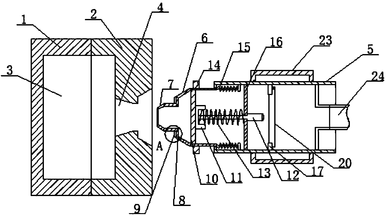
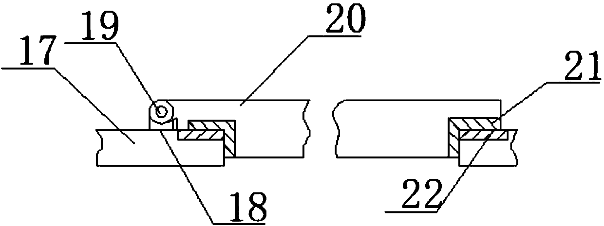
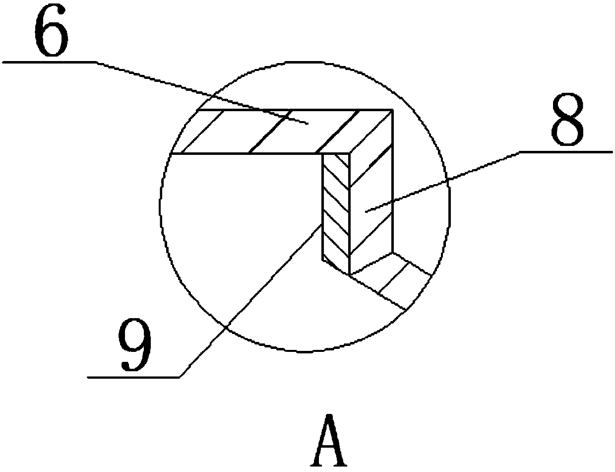
[0023] see Figure 1-Figure 3 As shown, a gas-assisted injection molding device that facilitates gas injection includes a fixed mold 1, a gas barrel 5 and a moving muzzle 6. The fixed mold 1 and the moving mold 2 are connected in contact, and the fixed mold 1 and the moving mold 2 can be easily separated. , to facilitate the removal of the plastic parts, the fixed mold 1 and the movable mold 2 are provided with a cavity 3, the cavity 3 matches the molded plastic part, and is used to shape the material, and the side of the movable mold 2 is provided with an injection port 4, While being used as the injection port of the material, the gun body can be supported. The gas gun barrel 5 is connected with the moving muzzle 6 through the elastic member 15, which can ensure the sealing performance while being connected to each other. The top of the moving muzzle 6 is provided with a The air port 7 and one side of the air outlet 7 are connected to the extruded end face 8, and the extrude...

Embodiment 2

[0025] In addition, refer to Figure 1-Figure 3 , based on the above embodiment, the fixed mold 1 is matched with the movable mold 2, and the fixed mold 1 and the movable mold 2 are connected in contact, and a matching cavity 3 is set in the fixed mold 1 and the movable mold 2, so that the device can inject the corresponding shape At the same time, it is convenient to take out the product. The injection port 4 is set obliquely. The shape of the injection port 4 matches the shape of the moving muzzle 6, so that the injection port 4 can be in close contact with the moving muzzle 6, which is easy to seal. The moving muzzle 6 can be horizontally direction to move a certain distance, the gas gun barrel 5 and the moving muzzle 6 are movably connected, so that the gun body can automatically open the compressed gas, which is convenient for the device to pass into the compressed gas. 8 is provided with a matching rubber ring 9, and the width of the extrusion end face 8 is set to match ...


PUM


Abstract

The invention discloses a gas-assisted injection molding device facilitating gas injection. The gas-assisted injection molding device comprises a fixed die, a movable die, a cavity, an injection molding port, a gas gun barrel, a movable gunpoint, a gas outlet, an extrusion end face, a rubber ring, a fixed rod, a clamping block, a limit feeler lever, a spring, a limit block, an elastic part, a limit rod, a connecting ring, a support rod, a rotating shaft, a sealing cover, a sealing ring, a gasket, a clamping rod and a compressed gas pipe. The gas gun barrel is connected with the movable gunpoint through the elastic part, sealing performance can be ensured while interconnection is realized, symmetric limit blocks are arranged on the movable gunpoint and can movably limit the gas gun barrel,supporting force is provided, the limit feeler lever is arranged in the movable gunpoint and can be abutted to the sealing cover, the sealing cover can be automatically opened, a compressed gas channel is connected, pressure can be continuously maintained, the limit feeler lever automatically springs back under the action of elastic force of the spring when being moved out of a gun, the compressedgas channel is closed, and gas is conveniently closed and opened.

Description

technical field [0001] The invention relates to an injection molding device, in particular to a gas-assisted injection molding device which facilitates gas injection, and belongs to the technical field of injection molding. Background technique [0002] The injection molding process is a very important technology type in the processing of plastic products. The processing of plastic parts in most industries requires the injection molding process to complete. It involves a wide range of industries and fields, such as food, electronic appliances, instruments, automobiles and motorcycles, daily use, chemical industry, agriculture, transportation and other industries can use plastic components manufactured by injection molding technology. [0003] The existing gas-assisted injection molding device uses compressed gas to pressurize the plastic parts. Ordinary gas injection is controlled by the switch on the gas pipe. The control of the compressed gas is not timely enough. When the...

Claims


Application Information

Patent Timeline
Patent Type & Authority Applications(China)
IPC IPC(8): B29C45/57B29C45/26B29C45/17
CPCB29C45/57B29C45/17B29C45/1734B29C45/26B29C45/2608
Inventor 蒙衍强陈卫民韦中明
Owner 柳州市鑫裕塑胶有限责任公司
Learn More