Conveying roll mechanism for automatic conveying line

A technology of conveying rollers and transportation lines, which is applied in the direction of conveyor objects, transportation and packaging, and rollers, and can solve the problems of roller mechanism wear, roller rotation restriction, and abnormal noise.

Inactive Publication Date: 2018-03-13
安徽纽创自动化装备有限公司
View PDF4 Cites 0 Cited by
  • Summary
  • Abstract
  • Description
  • Claims
  • Application Information

AI Technical Summary

Problems solved by technology

[0003] The purpose of the present invention is to provide a conveying roller mechanism for automatic transportation line, which solves the problem that whether it is a non-powered conveying roller or a driven conveying roller, the roll

Method used


Image

  • Conveying roll mechanism for automatic conveying line
  • Conveying roll mechanism for automatic conveying line

Examples


Embodiment Construction

[0027] Specific embodiments of the present invention will be described in detail below in conjunction with the accompanying drawings. It should be understood that the specific embodiments described here are only used to illustrate and explain the present invention, and are not intended to limit the present invention.

[0028] In the present invention, unless stated otherwise, the orientation words included in the term such as "radial direction" only represent the orientation of the term in the normal use state, or the common name understood by those skilled in the art, and should not be viewed as a limitation of this term.

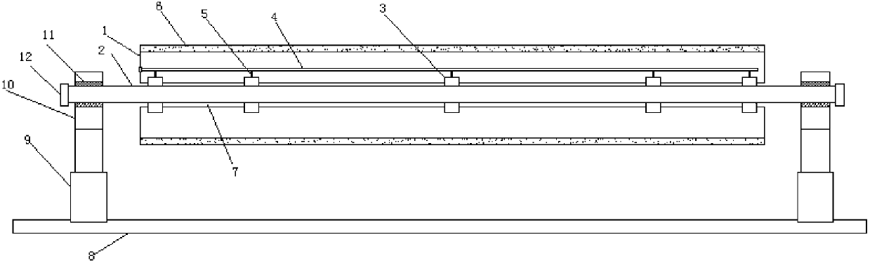
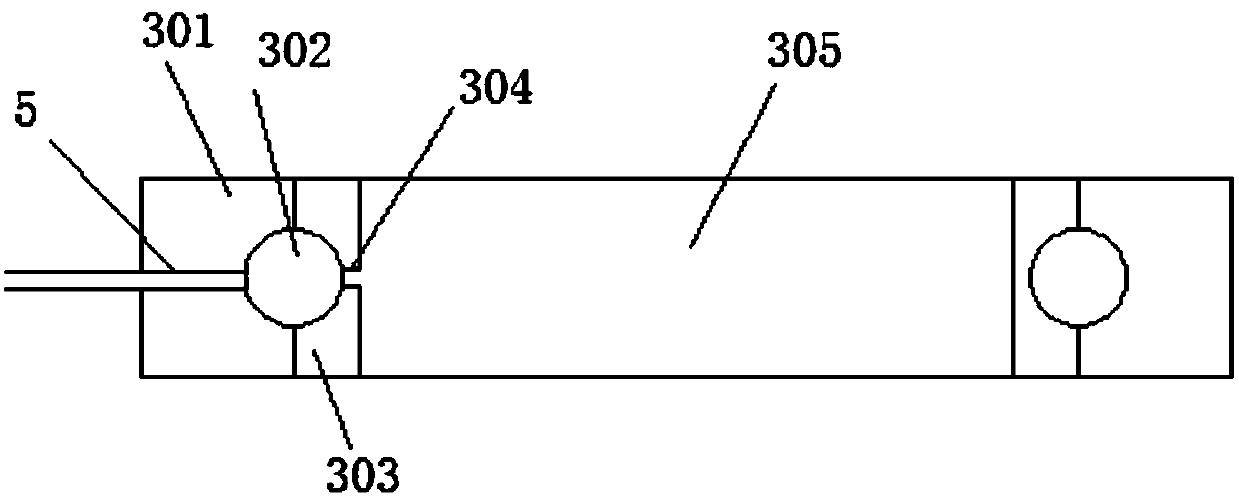
[0029] like figure 1 and figure 2 As shown: the present invention provides a conveying roller mechanism for an automatic transportation line, the conveying roller mechanism includes a roller 1 and a rotating shaft 2, and the roller 1 is provided with a penetrating hole along the length direction of the roller 1 The hole 7, the inner wall of the through...


PUM


Abstract

The invention discloses a conveying roll mechanism for an automatic conveying line. The conveying roll mechanism comprises a roller and a rotary shaft, a through slot is formed in the roller in the length direction of the roller, the inner wall of the through slot is concave inwards in the radial direction so that an annular clamping groove can be formed, a first bearing is fixed in the annular clamping groove, a through hole of the first bearing is made to be coaxial with the through slot, the rotary shaft penetrates through the through slot, and part of the rotary shaft is located in the through hole of the first bearing. By means of the conveying roll mechanism for the automatic conveying line, the problems that whether no power conveying roll exists or a drive conveying roll is provided, a roller mechanism is abraded after being used for a long time, rotation of the roller is limited if lubricating oil is not added in time, an abnormal sound is always made during operation, and theservice life of the roller is greatly shortened are solved.

Description

technical field [0001] The present invention relates to an automatic transport line, in particular to a conveying roller mechanism for an automatic transport line. Background technique [0002] There are two types of conveying rollers, which are unpowered and driven: unpowered conveying rollers are also called free rollers, which are composed of cylinders, shaft cores, deep groove ball bearings and bearing mounting frames, and are used for auxiliary rolling during use. , It has no power by itself, and it rolls by external force. Driven rollers generally refer to electric rollers with built-in motors. Here we also refer to rollers with sprockets, synchronous pulleys, etc. that can be driven by geared motors. The structure is basically the same as that of the unpowered, except that a motor is built in or other components such as a sprocket or a synchronous pulley are installed outside that can be driven by a geared motor. Regardless of whether it is a non-powered conveying r...

Claims


Application Information

Patent Timeline
IPC IPC(8): B65G39/09B65G39/02
CPCB65G39/02B65G39/09B65G2207/48
Inventor 陈文彬
Owner 安徽纽创自动化装备有限公司
Why Eureka
Try Eureka