Straw biomass vaporizing furnace

A biomass and gasification furnace technology, applied in incinerators, chemical instruments and methods, combustion methods, etc., can solve problems such as environmental pollution, air pollution, and inability to separate oil and gas well, and achieve environmental protection and health protection. Effect

Inactive Publication Date: 2018-03-13
安吉炜达锅炉成套设备有限公司
View PDF0 Cites 0 Cited by
  • Summary
  • Abstract
  • Description
  • Claims
  • Application Information

AI Technical Summary

Problems solved by technology

[0002] Energy issues are closely related to people's daily life, environment, economic development and the future of mankind. With the depletion of fossil fuels and the deterioration of the global environment, the development and utilization of renewable energy has been continuously concerned and valued by countries all over the world. China is a In a large agricultural country, a large amount of crop straw is produced every year. Before, these straws were mainly used for cooking by villagers in rural areas. With the use of liquefied gas in rural areas, most of the straws stacked in the fields were burned. Burning straws not only Wasted precious biomass resources, and also seriously polluted the environment. Now, the world, including China, has become increasingly serious about energy shortages, and is researching, developing and utilizing new energy sources, such as wind energy and solar energy. The development and utilization of straw has attracted great attention from the society. Domestic reports have researched and developed various types of straw vaporization utilization devices. The existing devices have a lot of tar, which cannot be effectively discharged, filtered and utilized, causing serious environmental pollution, and is also very easy to Blocking the pipeline; secondly, the oil and gas cannot be separated well, the content of soot in the fire is high, the smell of burning tar is serious, the air pollution is serious, and it causes great health hazards to the human body

Method used


Image

  • Straw biomass vaporizing furnace
  • Straw biomass vaporizing furnace

Examples


Embodiment Construction

[0013] The following will clearly and completely describe the technical solutions in the embodiments of the present invention with reference to the accompanying drawings in the embodiments of the present invention. Obviously, the described embodiments are only some, not all, embodiments of the present invention. Based on the embodiments of the present invention, all other embodiments obtained by persons of ordinary skill in the art without making creative efforts belong to the protection scope of the present invention.

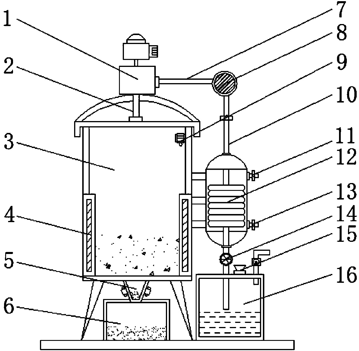
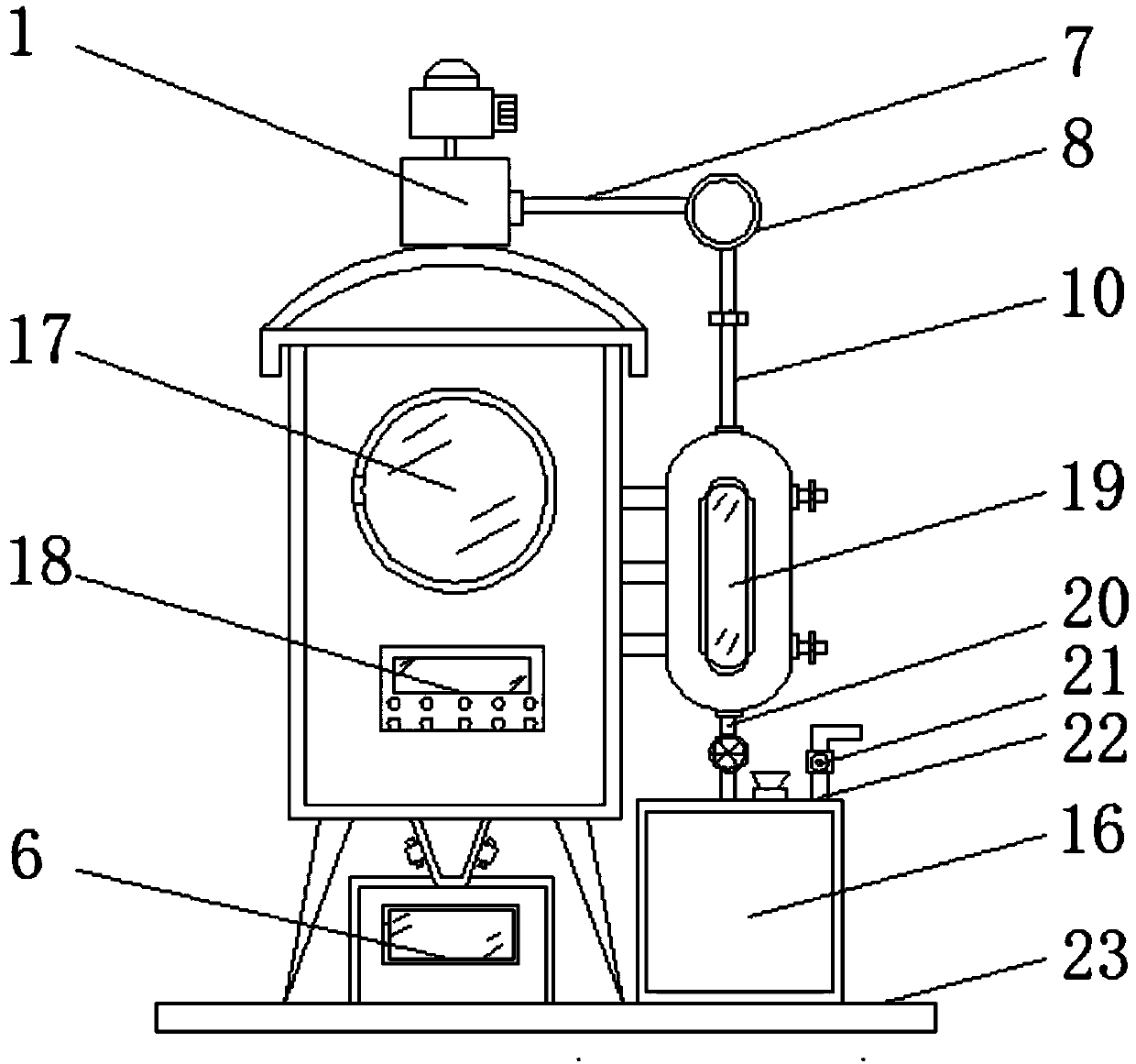
[0014] see Figure 1-2 , an embodiment provided by the present invention: a straw biomass gasification furnace, including an incineration chamber 3, a collection box 6, a condensation chamber 19 and a bottom plate 23, one end of the top of the bottom plate 23 is installed with an incineration chamber 3 through a support rod, and the incineration chamber 3 bottom plate 23 is equipped with collection box 6, the bottom end of incineration chamber 3 is connected w...


PUM


Abstract

The invention discloses a straw biomass vaporizing furnace. The straw biomass vaporizing furnace comprises an incineration chamber, a collecting box, a condensation chamber and a bottom plate. The incineration chamber is mounted at one end of the top of the bottom plate through a supporting rod; the collecting box is mounted on the bottom plate below the incineration chamber; the bottom end of theincineration chamber communicates to the top end of the collecting box through a discharge pipe; a vacuum pump is mounted at the top end of the incineration chamber, and the input end of the vacuum pump communicates to the inner part of the incineration chamber through an air inlet pipe; a temperature sensor is arranged at the top end in the incineration chamber; heating blocks are arranged on two sides in the incineration chamber; a charging opening is formed in one side of the incineration chamber; a control panel is mounted on the incineration chamber below the charging opening; and the condensation chamber is mounted at one end of the incineration chamber through the supporting rod. By mounting the heating blocks, the temperature sensor and the control panel, the temperature in the device is controlled conveniently, so that the temperature reaches the ignition point of the straws and the straws are incinerated thoroughly.

Description

technical field [0001] The invention relates to the technical field of a straw biomass gasification furnace, in particular to a straw biomass gasification furnace. Background technique [0002] Energy issues are closely related to people's daily life, environment, economic development and the future of mankind. With the depletion of fossil fuels and the deterioration of the global environment, the development and utilization of renewable energy has been continuously concerned and valued by countries all over the world. China is a In a large agricultural country, a large amount of crop straw is produced every year. Before, these straws were mainly used for cooking by villagers in rural areas. With the use of liquefied gas in rural areas, most of the straws piled up in the fields were burned. Burning straws not only Wasted precious biomass resources, and also seriously polluted the environment, now, the whole world including China, the problem of energy shortage is becoming mo...

Claims


Application Information

Patent Timeline
IPC IPC(8): F23G7/10F23J15/02F23J15/04B01D50/00
CPCF23G7/10F23J15/025F23J15/04F23G2209/262B01D50/60
Inventor 邹高峰
Owner 安吉炜达锅炉成套设备有限公司
Why Eureka
Try Eureka