Detection apparatus of bridge supporting seat

A detection device, bridge bearing technology, applied in the direction of measurement device, color TV parts, TV system parts, etc. The effect of simple operation and lower operating cost

Pending Publication Date: 2018-03-13
CHINA GEZHOUBA GRP HIGHWAY OPERATION CO LTD
View PDF4 Cites 4 Cited by
  • Summary
  • Abstract
  • Description
  • Claims
  • Application Information

AI Technical Summary

Problems solved by technology

[0005] The embodiment of the present application provides a detection device for a bridge support. The above-mentioned device solves the problem that in the prior art, when the bridge sidewalk is too wide to use a bridge detection vehicle or needs to build an underwater support, the cost is very large and detection personnel are required. Climbing, there are potential safety hazards, and the use of inspection vehicles requires personnel on the bridge to direct the traffic, which is a technical problem that wastes manpower. It achieves the technical effects of easy operation of the equipment, convenient preparation of inspection reports, elimination of potential safety hazards, and reduction of operating costs.

Method used


Image

  • Detection apparatus of bridge supporting seat
  • Detection apparatus of bridge supporting seat
  • Detection apparatus of bridge supporting seat

Examples


Embodiment 1

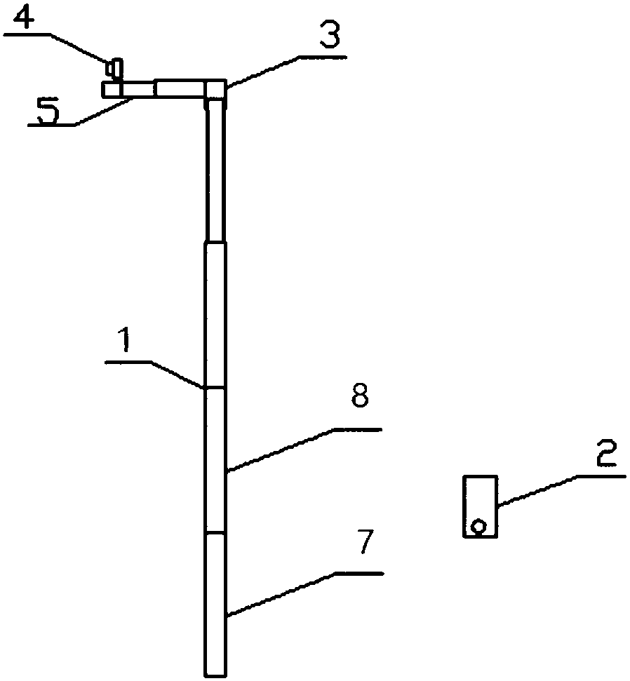
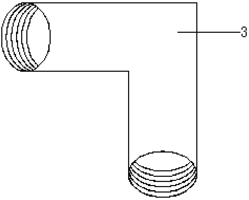
[0032] The embodiment of this application provides a detection device for bridge supports, please refer to figure 1 , figure 2 , image 3 , Figure 4 , the device includes:

[0033] detection rod;

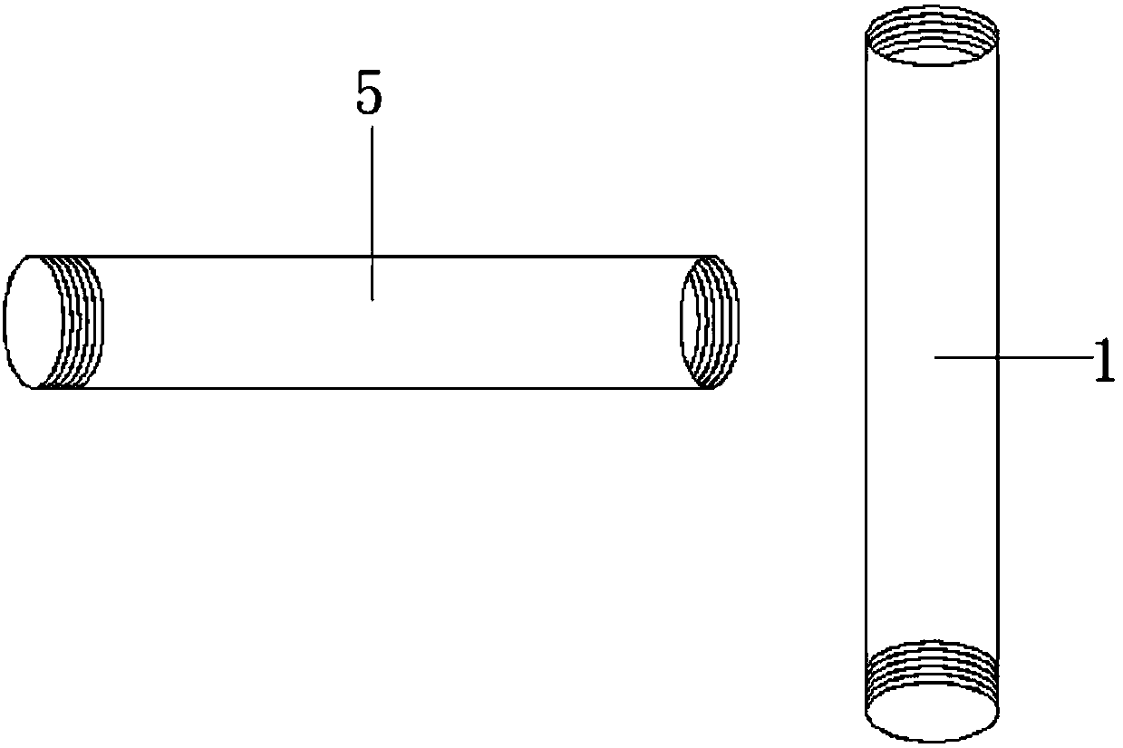
[0034] Further, the detection rod includes: a lifting rod 1; an outreach rod 5, one end of the outreach rod 5 is connected to the lifting rod 1, and the other end is rotatably connected to the camera 4, and the outreach rod 5 5 is a multi-stage telescopic rod structure; the elevating rod 1 includes: a first telescopic rod 7; a second telescopic rod 8, one end of the second telescopic rod 8 is telescopically connected to one end of the first telescopic rod 7; The second telescopic rod 8 and the first telescopic rod 7 are hollow tubes; the outer diameter of the second telescopic rod 8 matches the inner diameter of the first telescopic rod 7, so that the second telescopic rod 8 It can be stretched inside the first telescopic rod 7; a locking mechanism is provided between the sec...

Embodiment 2

[0042] The embodiment of this application provides a working method of the detection device of the bridge support, please refer to figure 1 , figure 2 , image 3 , Figure 4 , the specific working method is:

[0043] (1) Determine the height of the elevating rod 1 according to the height of the pier, then stretch the elevating rod 1 section by section, and rotate and fix until the height of the elevating rod 1 is higher than the top of the pier;

[0044] (2) Determine the length of the outrigger 5 according to the width of the bridge pier, then stretch the outrigger 5 bar section by section, and rotate and fix until the length of the outrigger 5 can observe the side conditions of the bridge support;

[0045] (3) Fix the lifting rod 1 and the outrigger 5 through the connector 3, first rotate the connector 3 to the lifting rod 1, and then rotate the outrigger 5 fixed to the connector 3;

[0046] (4) fixing the camera 4 on the outrigger 5 by means of clips or inlays;

[00...


PUM


Abstract

The invention discloses a detection apparatus of a bridge supporting seat, which relates to the technical field of bridges. The detection apparatus comprises a detection rod, a camera and an electronic device, wherein the camera is fixedly connected with one end of the detection rod; and the electronic device can be connected with the camera so as to control the camera. By adopting the detection apparatus, the technical problems in the prior art that when a bridge pedestrian is excessively wide, a bridge detection cart cannot be used or when an underwater support is needed, the cost is high, the detection personnel needs to climb, the safety potential danger exists, the use of the detection cart needs the personnel on the bridge to direct the traffic and the manpower is wasted can be solved, and the technical effects that the device is simple in operation, the detection report is convenient to edit, the safety potential danger is eliminated, and the operation cost is reduced can be achieved.

Description

technical field [0001] The invention relates to the technical field of bridges, in particular to a detection device for bridge supports. Background technique [0002] At present, when performing bridge appearance inspection, the conventional inspection methods are to build supports or use bridge inspection vehicles, but these methods are not applicable or expensive in some occasions. [0003] However, in the process of implementing the technical solutions in the embodiments of the present application, the inventors of the present application found that the above-mentioned prior art has at least the following technical problems: [0004] In the prior art, when the sidewalk of the bridge is too wide to use the bridge inspection vehicle or need to build an underwater support, the cost is very high, and inspection personnel are required to climb, which has potential safety hazards, and the use of the inspection vehicle requires personnel on the bridge to direct traffic , a tech...

Claims


Application Information

Patent Timeline
Patent Type & Authority Applications(China)
IPC IPC(8): G01D21/00H04N5/225
CPCG01D21/00H04N23/56H04N23/50
Inventor 李振珂房铁柱屈庆余郭璞
Owner CHINA GEZHOUBA GRP HIGHWAY OPERATION CO LTD
Why Eureka
Try Eureka