Supercharge Your Innovation With Domain-Expert AI Agents!

Verification system and method for online monitoring device of onsite capacitive equipment

A technology of capacitive equipment and monitoring devices, applied in the direction of measuring devices, measuring electricity, measuring electrical variables, etc., can solve problems such as difficult on-site handling, very long stretching, signal distortion, etc., achieve strong anti-electromagnetic field interference performance, save The effect of line take-up, amplitude and phase stability

Pending Publication Date: 2018-03-13
STATE GRID CORP OF CHINA +4
View PDF6 Cites 6 Cited by
  • Summary
  • Abstract
  • Description
  • Claims
  • Application Information

AI Technical Summary

Problems solved by technology

[0004] The traditional line monitoring device has a calibration method of standard voltage plus standard resistance and capacitance, but to generate a current of any size and angle, the number of standard resistance and capacitance required is very large, the volume is large, the weight is heavy, it is not easy to carry on site, and the adjustment The resolution is not high; in addition, the existing wired way to take the PT voltage reference has the following problems: when the PT voltage device is far away from the capacitive equipment at the calibration point, a long signal line needs to be pulled, and the signal will be distorted and attenuated; When the calibration point is moved to the calibration system, it is necessary to manually receive and release the signal line, which wastes manpower and time, and the calibration efficiency is low

Method used


Image

  • Verification system and method for online monitoring device of onsite capacitive equipment
  • Verification system and method for online monitoring device of onsite capacitive equipment
  • Verification system and method for online monitoring device of onsite capacitive equipment

Examples


Embodiment Construction

[0042] The technical solutions in the present invention will be clearly and completely described below in conjunction with the accompanying drawings in the present invention.

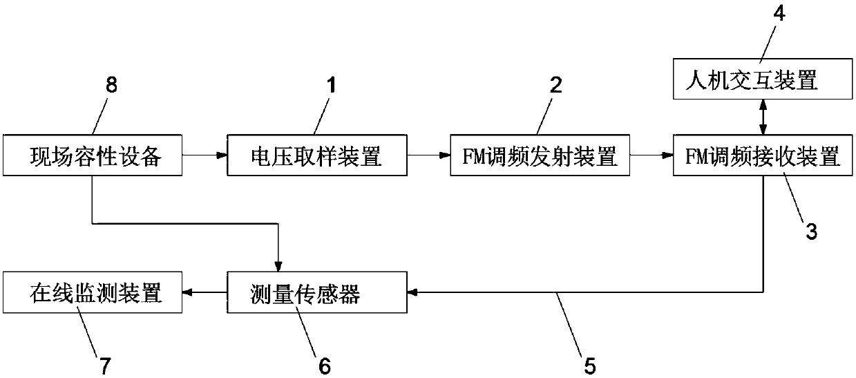
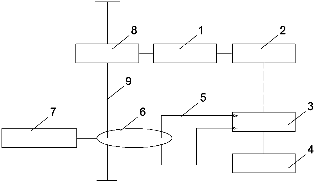
[0043] Such as figure 1 and figure 2 As shown, the verification system of a field capacitive equipment on-line monitoring device provided by the present invention includes a voltage sampling device 1, an FM frequency modulation transmitting device 2, an FM frequency modulation receiving device 3, a human-computer interaction device 4, a current output wire 5 and Measuring sensor6.

[0044] Described voltage sampling device 1 is connected with the voltage input terminal of on-site capacitive equipment 8, is used to obtain the operation reference voltage of on-site capacitive equipment 8, and transmits to FM frequency modulation transmitting device 2, and voltage sampling device 1 is in the present embodiment High precision transformer;

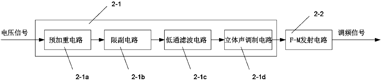
[0045] The FM FM transmitting device 2 is connected with the vo...


PUM


Abstract

The invention provides a verification system and method for an online monitoring device of onsite capacitive equipment, and the calibration system comprises a voltage sampling device, an FM (frequencymodulation) transmitting device, an FM receiving device, a human-machine interaction device, a current output wire, and a measurement sensor. The verification method comprises the steps: firstly obtaining a PT voltage signal corresponding to the onsite capacitive equipment as an operation reference voltage signal through the voltage sampling device; secondly modulating the operation reference voltage signal into a composite audio signal through the FM transmitting device, carrying out the frequency modulation transmission, transmitting the composite audio signal to the FM receiving device through wireless transmission, and outputting a reference current signal which has the same frequency as the PT reference voltage and has the programmable phase and amplitude after the demodulation, programmable amplitude and phase modulation and amplification; thirdly carrying out the parameter overlapping of the reference current signal and an initial current signal of the online monitoring device,and obtaining a current, a capacitance and a dielectric loss theoretical increment; fourthly injecting the reference current signal into the online monitoring device, and measuring the actual current, capacitance and dielectric loss increment through the online monitoring device; finally comparing the theoretical increment with the actual increment, and verifying whether the online monitoring device is qualified or not.

Description

technical field [0001] The invention relates to the field of on-line monitoring of electric power equipment, in particular to a verification system and a verification method of an on-site capacitive device on-line monitoring device. Background technique [0002] When the high-voltage electrical equipment operating in the power grid has insulation defects caused by factors such as poor manufacturing, aging, and external damage, it will cause equipment failure or insulation accidents, which will seriously affect the normal operation of the power grid. In order to prevent such major safety accidents, the current traditional method is to regularly cut off the power for preventive tests and maintenance after the equipment is put into operation, so as to detect the insulation defects inside the equipment in time. However, the test conditions of the power failure preventive test are quite different from the operating state. The dielectric loss test is usually tested at a voltage of...

Claims


Application Information

Patent Timeline
IPC IPC(8): G01R31/00G01R35/00
CPCG01R31/00G01R35/00
Inventor 张露贺家慧王永勤吴彤罗浪冯凝邵华锋李小双
Owner STATE GRID CORP OF CHINA
Features
  • R&D
  • Intellectual Property
  • Life Sciences
  • Materials
  • Tech Scout
  • Unparalleled Data Quality
  • Higher Quality Content
  • 60% Fewer Hallucinations
Learn More