
Junction box

A junction box and box body technology, applied in the field of junction boxes, can solve the problems of small size of split junction boxes, high requirements for heat dissipation, and inability to be universal, and achieve the effects of compact structure, improved reliability, and improved utilization.

Pending Publication Date: 2018-03-13
浙江正泰鑫辉光伏有限公司
View PDF0 Cites 0 Cited by
  • Summary
  • Abstract
  • Description
  • Claims
  • Application Information

AI Technical Summary

Problems solved by technology

[0003] The disadvantage of the existing split junction box is that the size of the split junction box is small, and the requirements for internal heat dissipation are very high. The diode and the bus strip on the terminal strip are important heating elements, and both of them are narrow inside the split junction box. The positions are close in space, the heat is relatively concentrated and interacts with each other
In addition, due to the different structures of each junction box in the split junction box, there are many kinds of parts and generally cannot be used in common
In practical applications, the split junction box is suitable for both double-sided bus strips and single-sided bus strips. The existing split junction box structure cannot meet the above-mentioned multiple applications at the same time, so different bus belt components for customers , it is necessary to design different junction box structures, and the cost is high

Method used


Image

  • Junction box
  • Junction box
  • Junction box

Examples


Embodiment Construction

[0026] The specific embodiments of the present invention will be further described below in conjunction with the accompanying drawings.

[0027] The junction box of the present invention is a split type junction box, and the following embodiments are described by taking a three-split type junction box with an intermediate box body as an example.

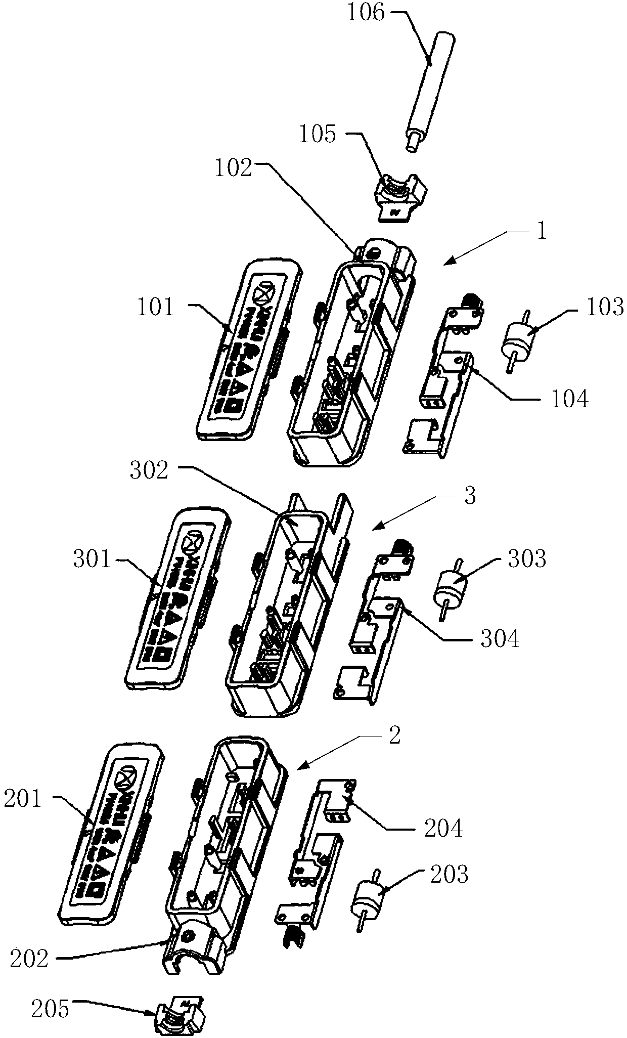
[0028] figure 1 Shown is an exploded structure of an embodiment of the present invention, which includes a positive electrode box body 1, a negative electrode box body 2 and at least one intermediate box body 3, the positive electrode box body 1 includes a matched positive electrode cover 101 and a positive electrode base 102, and the negative electrode box body The body 2 includes a matching negative electrode cover 201 and a negative electrode base 202 , and the middle box body 3 includes a matching middle cover 301 and a middle base 302 . The positive base 102, the negative base 202, and the intermediate base 302 are respectively...


PUM


Abstract

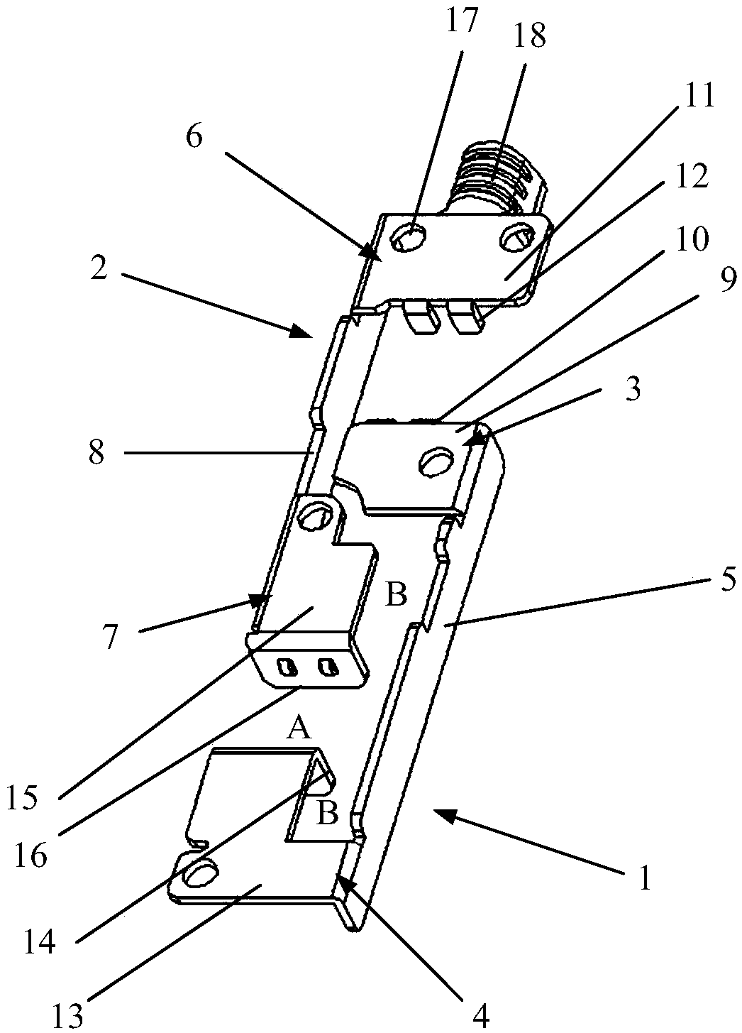
The present invention discloses a junction box. The junction box comprises a positive electrode box body, a negative electrode box body and 0-N middle box bodies. Each box body comprises one lid and one pedestal which are cooperated; each pedestal is internally provided with one diode and one terminal sheet electrically connected with the diode; and each bus bar is connected with each terminal sheet, and a leading-out terminal of a photovoltaic cable is connected with the terminal sheets. Each terminal sheet comprises two metal sheets, each metal sheet comprises one diode connection portion, one bus bar connection portion and one strip plate connected with the diode connection portion and the bus bar connection portion, the diode connection portion and the bus bar connection portions of the two metal sheets are in staggered arrangement, and the terminal sheets are compact in structure, small in box body width, better in heat dissipation and higher in photovoltaic power generation efficiency. Bus bar welding points are connected with diode welding points through the strip plates, heat effect therebetween is small, and low-temperature soldering tin is not easy to fall off. The diodesare installed close to the cable, and are good in heat dissipation. The terminal sheets are the same in structure, support dual-sided or single-sided module bus bars, and can form standardization. Four pillars of each pedestal are taken as reinforcing ribs to prevent from thermal deformation and mechanical shock, and are also buckle areas of the pedestal and the lids, wherein the misalignment design of the buckle areas of the pedestal and the lids can prevent from reverse installation.

Description

technical field [0001] The invention belongs to the field of structural design of a photovoltaic junction box, and in particular relates to a junction box. Background technique [0002] The photovoltaic junction box is an important part used to connect photovoltaic module panels and inverters in solar power generation systems. The split junction box is a kind of junction box. The traditional junction box is decomposed into a positive junction box, a negative junction box and several intermediate junction boxes. Each junction box is equipped with a diode, and each junction box is directly connected to the phase. Between adjacent battery packs, the photovoltaic cables are only connected to the positive junction box and the negative junction box. The split junction box can minimize the connection length and disperse the heat of the diodes. At the same time, the electrical components in the intermediate junction box can be pre-sealed. During on-site installation, only the posit...

Claims


Application Information

Patent Timeline
Patent Type & Authority Applications(China)
IPC IPC(8): H02S40/34
CPCH02S40/34H02S40/345Y02E10/50
Inventor 彭祁军李艳群徐林峰叶炳恽旻
Owner 浙江正泰鑫辉光伏有限公司
Learn More