Rotary cultivator

The technology of a rotary tiller and a rotary tiller, which is applied in the field of rotary tiller, can solve problems such as sinking or prying up of rotary tiller blades, inconsistent crop growth, and heavy labor workload of operators, and achieve consistent rotary tillage depth and compact structure , the effect of increasing the range of use

Inactive Publication Date: 2018-03-16
天津牧耘科技有限公司
8 Cites 2 Cited by

AI-Extracted Technical Summary

Problems solved by technology

Its operating depth is an important performance indicator, usually the operating depth is generally 8-15cm, and the operating depth is limited by the maximum turning radius of the rotary tiller, the position of the lowest point of the cutter shaft support such as the transmission box and the support plate, and the matching Due to the influence of power, deeper operations cannot be completed. Long-term use of rotary tillers for plowing operations will make the soil plow layer shallower, and the soil hardening layer will rise, which affects the growth of crops.
[0004] At the same time, when the rotary tiller is performing rotary tillage on re...

Method used

Above-mentioned traveling mechanism comprises wheel, front axle and rear axle, and traveling mechanism is used for carrying rotary tillage device to move forward, and completes rotary tillage operation, and the two ends of front axle and rear axle are connected with wheel respectively, by The rotation of the wheels drives the front axle and the rear axle to move forward, and the running mechanism also includes an engine and a gearbox to provide power for the running mechanism. The number of the wheels is an even number, preferably 4, and the wheels include a cylindrical The wheel body forms outward flanges at both ends of the cylindrical wheel body. These two flanges form an annular groove with the outer wall of the wheel body. If there are two anti-skid sheets, multiple anti-skid sheets are located in the annular groove. The setting of anti-skid sheets improves the anti-skid performance of the wheel and improves the grip of the wheel at the same time. The cylindrical wheel increases the contact area between the wheel and the soil and prevents rotation. The tiller sinks into the field, which can ensure the continuous operation of the rotary tiller. In addition, the anti-slip sheet in the annular groove is vertically arranged.
As shown in Figure 1, the present invention relates to a kind of rotary tiller, is used for the rotary tillage of land, and soil is broken, and makes soil loose and broken, is convenient to the cultivation of crops. The rotary tiller comprises a rotary tiller 3, a walking device, a pressure adjustment device 4, a power system 2 and a control system. The system 2 is connected to the control system, and the power system 2 and the control system are both arranged on the rotary tiller 3. The rotary tiller 3 includes a first cutter shaft and a second cutter shaft, and the first cutter shaft and the second cutter shaft pass through the transmission mechanism respectively. Connect with Powertrain 2. The rotary tillage device 3 is used to perform rotary tillage on the land, and the traveling mechanism is used to carry the rotary tiller device 3 for walking to complete the rotary tillage of the land. The power system 2 provides power for the rotation of the rotary tiller device 3, so that the The first rotating shaft 30 and the second rotating shaft 31 rotate at the same time to carry out two-axis rotary tillage, so that the rotary tillage efficiency of the rotary tiller is improved. The pressure is adjusted to ensure the leveling of the land after rotary tillage. In addition, the control system is electrically connected to the power system. The control system controls the speed of the motor in the power system 2 to control the speed of the first rotating shaft 30 and the second rotating shaft 31, so that the first rotating shaft 30 and the rotational speeds of the second rotating shaft 31 are controlled, thereby making the rotary tiller more applicable.
As shown in Figures 2 and 3, above-mentioned rotary tillage device 3 also includes support plate 13, fixed frame 1, first rotating shaft 30, second rotating shaft 31 and mounting plate, and support plate 13 is used for the installation of power system 2 support, the power system 2 is installed on the support plate 13, the first rotating shaft 30 and the second rotating shaft 31 are fixedly installed on the lower part of the supporting plate 13, and the two ends of the first rotating shaft 30 and the second rotating shaft 31 are respectively installed on the The lower surface of the support plate 13, and the first rotating shaft 30 and the second rotating shaft 31 are arranged in sequence, and there is a certain gap between the two, so as to ensure that the tools on the first rotating shaft 30 and the second rotating shaft 31 will not produce frictional collisions, To avoid mutual influence during work, at the same time, the height of the first rotating shaft 30 and the second rotating shaft 31 can be kept at the same height, and can also be kept at different heights. Preferably, the first rotating shaft 30 and the second rotating shaft 31 are kept at different heights. When the first rotating shaft 30 and the second rotating shaft 31 are not at the same height, the rotary tiller can be used for rotary tillage on uneven land, so that the rotary tiller can be applied to different land conditions, ensuring that the upper plow layer soil It does not mix with the lower raw soil to ensure the production environment of crops. The first rotating shaft 30 and the second rotat...

Abstract

The invention provides a rotary cultivator. The rotary cultivator comprises a rotary cultivating device, a walking device, a pressing device, a power system and a control system, wherein the rotary cultivating device is arranged at the tail end of the walking device; the pressing device is arranged at the tail end of the rotary cultivating device; the power system is connected with the control system; both the power system and the control system are arranged on the rotary cultivating device; the rotary cultivating device comprises a first cutter shaft and a second cutter shaft; the first cutter shaft and the second cutter shaft are connected with the power system through the transmission mechanism. The rotary cultivator has the beneficial effects that a fixing frame is adopted, the rotarycultivating device is suspended on the walking mechanism through an upper pull rod, a lower pull rod and a lifting device, and the ascending and descending of the rotary cultivating device are controlled through the lifting device in order to prevent a rotary cultivation tool from sinking and ensure that the rotary cultivating depth is always constant when the rotary cultivating device works on uneven ground; the first cutter shaft and the second cutter shaft are arranged one after the other, so that the power consumption of the whole rotary cultivator is lower, upper cultivated soil is prevented from being mixed with lower raw soil, the production environment of crops is ensured, and the operation cost is lowered.

Application Domain

Tilling equipments

Technology Topic

Fixed frameEngineering +6

Image

  • Rotary cultivator
  • Rotary cultivator
  • Rotary cultivator

Examples

  • Experimental program(1)

Example Embodiment

[0036] The present invention will be further described below in conjunction with the accompanying drawings and specific embodiments.
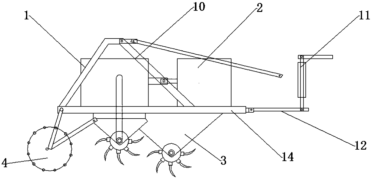
[0037] like figure 1 As shown, the present invention relates to a rotary tiller, which is used for rotary tillage of the land and crushes the soil so that the soil is loose and broken, which is convenient for the cultivation of crops. The rotary tiller comprises a rotary tiller 3, a walking device, a pressure adjustment device 4, a power system 2 and a control system. The system 2 is connected to the control system, and the power system 2 and the control system are both arranged on the rotary tiller 3. The rotary tiller 3 includes a first cutter shaft and a second cutter shaft, and the first cutter shaft and the second cutter shaft pass through the transmission mechanism respectively. Connect with Powertrain 2. The rotary tillage device 3 is used to perform rotary tillage on the land, and the traveling mechanism is used to carry the rotary tiller device 3 for walking to complete the rotary tillage of the land. The power system 2 provides power for the rotation of the rotary tiller device 3, so that the The first rotating shaft 30 and the second rotating shaft 31 rotate at the same time to carry out two-axis rotary tillage, so that the rotary tillage efficiency of the rotary tiller is improved. The pressure is adjusted to ensure the leveling of the land after rotary tillage. In addition, the control system is electrically connected to the power system. The control system controls the speed of the motor in the power system 2 to control the speed of the first rotating shaft 30 and the second rotating shaft 31, so that the first rotating shaft 30 and the rotational speeds of the second rotating shaft 31 are controlled, thereby making the rotary tiller more applicable.
[0038] like figure 2 and 3 As shown, the above-mentioned rotary tillage device 3 also includes a support plate 13, a fixed frame 1, a first rotating shaft 30, a second rotating shaft 31 and a mounting plate, the supporting plate 13 is used for the support of the installation of the power system 2, and the power system 2 is installed on On the support plate 13, the first rotating shaft 30 and the second rotating shaft 31 are fixedly installed on the lower part of the supporting plate 13, and the two ends of the first rotating shaft 30 and the second rotating shaft 31 are respectively installed on the lower surface of the supporting plate 13 through the mounting plate, and The first rotating shaft 30 and the second rotating shaft 31 are arranged in sequence, and there is a certain gap between the two, so as to ensure that the tools on the first rotating shaft 30 and the second rotating shaft 31 will not have frictional collisions, and avoid mutual influence during work. At the same time, the height of the first rotating shaft 30 and the second rotating shaft 31 can be maintained at the same height or at different heights. Preferably, the first rotating shaft 30 and the second rotating shaft 31 are maintained at different heights. When the first rotating shaft 30 When it is not at the same height as the second rotating shaft 31, the rotary tiller can perform rotary tillage on uneven land, so that the rotary tiller can be applied to different land conditions, ensuring that the soil in the upper plow layer is not mixed with the raw soil in the lower part, ensuring In the production environment of crops, the first rotating shaft 30 and the second rotating shaft 31 are connected to the mounting plate through bearings, so that the first rotating shaft 30 and the second rotating shaft 31 can rotate on the mounting plate.
[0039] In addition, multiple sets of first cutter shafts are installed on the first rotating shaft 30, such as Figure 4-6As shown, and the number of the first cutter shafts is selected according to the actual needs, each first cutter shaft is equipped with a tool for rotary tillage of the land, to further optimize the scheme, there are multiple first shafts on the 30th row A groove 300, preferably, the number of the first groove 300 is three, and the first groove 300 extends from the surface of the first rotating shaft 30 from one end of the first rotating shaft 30 to the other end, and the first groove The groove 300 is parallel to the center line of the first rotating shaft 30, the first grooves 300 are evenly distributed on the circumferential side of the first rotating shaft 30, and a plurality of The first bump 302, the number of the first bump 302 is the same as the number of the first groove 300, then preferably, the number of the first bump 302 is three, at the same time, the first groove 300 is the same as the first groove 300 The shape and size of the block 302 are adapted so that the first protrusion 302 can be inserted into the first groove 300, so that the first knife shaft and the first rotating shaft 30 will not rotate relative to each other. In addition, on the first rotating shaft 30, adjacent A first rotating shaft screw hole 301 is provided between the two first grooves 300, and a first cutter shaft screw hole 303 is provided between two connected protrusions 302 on the first cutter shaft, and the first cutter shaft screw hole 303 is a through hole, the first rotating shaft screw hole 301 is adapted to the shape and size of the first cutter shaft screw hole number 303, and the position is also adapted, so that the first cutter shaft and the first rotating shaft 30 pass through the first rotating shaft screw hole 301 and the first rotating shaft screw hole 301. The first cutter shaft screw holes 303 are fixedly connected, and the number of the first rotating shaft screw holes 301 between two adjacent first grooves 300 is multiple, and they are evenly arranged, so that when a plurality of first cutter shafts are installed , the distance between two adjacent first cutter shafts can be selected according to requirements, so that the distance between the first cutter shafts can be adjusted, and at the same time, the range of use of the rotary tiller can be increased.
[0040] Similarly, the structure and connection mode of the second rotating shaft 31 and the second cutter shaft are the same as those of the first rotating shaft 30 and the first cutter shaft, that is, multiple groups of second cutter shafts are installed on the second rotating shaft 31 , and the number of the second cutter shafts is selected according to the actual needs. Each second cutter shaft is equipped with a tool for rotary tillage of the land. To further optimize the scheme, a plurality of second recesses are arranged on the second rotating shaft 31 rows groove, preferably, the number of the second groove is three, and the second groove extends from the surface of the second rotating shaft from one end of the second rotating shaft to the other end, and the second groove and the second rotating shaft 31 The center lines are parallel, the second grooves are evenly distributed on the circumferential side of the second rotating shaft 31, and a plurality of second protrusions are arranged on the inner surface of the second cutter shaft and the surface in contact with the second rotating shaft 31. The number of blocks is the same as the number of the second groove, then preferably, the number of the second protrusion is three, and at the same time, the second groove is adapted to the shape and size of the second protrusion, so that the second protrusion can be inserted In the second groove, the second cutter shaft and the second rotating shaft will not rotate relative to each other. In addition, on the second rotating shaft, a second rotating shaft screw hole is provided between two adjacent second grooves. A second cutter shaft screw hole is provided between the two connected protrusions on the cutter shaft, and the second cutter shaft screw hole is a through hole, and the number and shape of the second rotating shaft screw hole are adapted to the second cutter shaft screw hole And the position is also adapted, so that the second cutter shaft and the second rotating shaft 31 are fixedly connected with the second rotating shaft screw hole through the second rotating shaft screw hole, and the second rotating shaft screw hole between two adjacent second grooves The number is multiple, and they are evenly arranged, so that when multiple second cutter shafts are installed, the distance between two adjacent second cutter shafts can be selected according to requirements, so that the distance between the second cutter shafts can be adjusted, and at the same time The range of use of the rotary tiller is increased.
[0041] In a further optimization scheme, the above-mentioned power system includes a power output shaft 20, a first transmission shaft 23, a second transmission shaft 24, a first gearbox assembly 21 and a second gearbox assembly 22, and the power output shaft 20 is a gearbox. The input end of the power output shaft 52 is connected with the motor, and the output end of the power output shaft 20 is connected with the first transmission shaft 23 and the second transmission shaft 24 respectively, and the first transmission shaft 23 and the second transmission shaft 24 are cardan shafts , and the first transmission shaft 23 and the second transmission shaft 24 are symmetrically distributed on both sides of the power output shaft 20, and are respectively connected with the power output shaft 20 through a coupling. In addition, the power output shaft 20 and the first transmission shaft can also be Devices such as a speed reducer are arranged between the shaft 23 and the second transmission shaft 24, and are selected according to actual needs. The other end of the first transmission shaft 23 is connected to the input end of the first gear box assembly 21, and the first gear box assembly 21 The output end of the output end is connected with one end of the first rotating shaft 30, so that the rotation of the power output shaft 20 is transmitted to the first rotating shaft 30 through the first transmission shaft 23 and the first gear box assembly 21, and then drives the first cutter shaft to rotate; similarly, The other end of the second transmission shaft 24 is connected with the input end of the second gear box assembly 22, and the output end of the second gear box assembly 22 is connected with one end of the second rotating shaft 31, and the rotation of the power output shaft 20 is passed through the second The transmission shaft 24 and the second gear box assembly 22 are transmitted to the second rotating shaft 31, and then drive the second cutter shaft to rotate. Since the power output shaft 20 is coaxially connected with the first transmission shaft 23 and the second transmission shaft 24 respectively, the first A transmission shaft 23 rotates synchronously with the second transmission shaft 24, which ensures that the first rotating shaft 30 and the second rotating shaft 31 rotate synchronously, so that the first rotating shaft 30 and the second rotating shaft 31 have the same rotational speed, ensuring that the first cutter shaft and the second rotating shaft 31 have the same rotational speed. The second cutter shaft rotates synchronously, which ensures that the rotation speed of the first cutter shaft and the second cutter shaft are the same, so that the first cutter shaft and the second cutter shaft perform rotary tillage work at the same time, which improves the working efficiency of the whole machine and reduces the power consumption of the whole machine. consumption.
[0042] The above-mentioned traveling mechanism includes wheels, front axle and rear axle. The traveling mechanism is used to carry the rotary tillage device forward to complete the rotary tillage operation. The front axle and the rear axle move forward, and the running mechanism also includes an engine and a gearbox to provide power for the running mechanism. The number of the wheels is an even number, preferably 4, and the wheels include a cylindrical wheel body. The two ends of the cylindrical wheel body form outward flanges, and the two flanges form an annular groove with the outer wall of the wheel body, and a plurality of anti-slip sheets are arranged along the circumferential side of the outer wall surface of the wheel body , then a plurality of anti-slip sheets are located in the annular groove, the setting of the anti-slip sheets improves the anti-slip performance of the wheel, and at the same time improves the grip of the wheel. The cylindrical wheel increases the contact area between the wheel and the soil, preventing the rotary tiller from falling into In the field, the continuous work of the rotary tiller can be guaranteed. In addition, the anti-slip sheet in the annular groove is vertically arranged.
[0043] To further optimize the scheme, the above-mentioned fixed frame 1 includes a pull-up rod 10, a pull-down rod 12 and a lifting device 11, and the pull-up rod 10 includes a pull-up rod 1, a pull-up rod 2 and a pull-up rod 3, and one end of the pull-up rod 1 and the rear end of the support plate 13 The upper surface is hinged, one end of the upper tie rod two is hinged with the upper surface of the front end of the support plate 13, the other end of the upper tie rod one is hinged with the other end of the upper tie rod two, and one end of the upper tie rod three is connected with the upper tie rod one and the upper tie rod two. The articulated end is hinged, the other end of the upper tie rod 3 is hinged with the rear axle, and the rotary tiller 3 is installed behind the walking structure. The upper tie rod 10 has two sets of the same structure, which are symmetrically arranged on the left and right sides of the support plate 13, so that Both sides of the support plate 13 are evenly stressed, one end of the lower rod 12 is hinged with the front end of the support plate 13, the other end of the lower rod 12 is connected with the lifting device 11, the other end of the lifting device 11 is connected with the rear axle, and the lifting device 11 is connected to the control system in the traveling mechanism, and the control system in the traveling mechanism controls the lifting of the lifting device 11. Here, the lifting device 11 is a hydraulic device, or a pneumatic device, or other mechanical structures, which can be selected according to actual needs , the lifting device 11 controls the lifting of the rotary tiller 3. When the rotary tiller 3 is operating, the operator only needs to operate in the traveling mechanism to lower the rotary tiller 3, so that the cutter on the rotary tiller and the soil Contact, perform rotary tillage operation, when the rotary tillage operation is completed, the operator raises the lifting device 11 through the control system in the traveling mechanism, and raises the rotary tillage device 3 to avoid that the rotary tiller device 3 is not in contact with the soil during operation, cause damage to the tool. The control system in the running gear is the same as that of the tractor that is generally used now, and the running gear can also be a tractor, and the wheels of the tractor can also be replaced with the above-mentioned wheel structure.
[0044] In addition, the power system provided on the top of the rotary tiller 3 is also connected with a control system, the control system includes a power supply module, a regulating switch and a control module, the power supply module is electrically connected to the motor through the control module, and the motor is connected to the power output shaft to control The module is electrically connected with the regulating switch. The power supply module is connected to the motor through the control module and supplies power to the motor. The current of the circuit is changed through the control module, and the working voltage on the motor is changed to change the speed of the motor. The control module and the adjustment switch are connected through wires to adjust The switch is used to control the magnitude of the current of the control module, and then change the magnitude of the current of the circuit, so that the operating voltage of the motor and the speed of the motor change accordingly, and the motor and the input end of the power output shaft 20 are connected through a coupling. The change of the motor speed makes the speed of the power output shaft 20 change correspondingly, which in turn causes the gear transmission speed in the gearbox assembly to change, and finally makes the speed of the first rotating shaft and the second rotating shaft in the rotary tillage device change, thereby changing the cutter shaft. The rotation speed of the cutter shaft can be adjusted to adapt to different soils. For soft and hard soils, change the rotation speed of the shaft to adapt to different soils and prolong the service life of the cutter. At the same time, the rotary tiller machine Lowest power consumption.
[0045] The rectification device 4 is installed on the end of the support plate 13, positioned at the rear and lower part of the support plate 13. The rectification device 4 is located at the back of the rotary tiller 3, and the land that the rotary tiller 3 has completed is rectified. 4 and the rotary tillage device 3 are provided with a mud scraper to scrape off the soil on the pressure adjustment device 4 . The pressure adjustment device 4 comprises a central shaft, a compression bar 41, a circular support plate 40 and a connecting plate, one end of the connecting plate is hinged to the end of the supporting plate 13, and the other end of the connecting plate is connected to the central shaft through a bearing, and the number of the connecting plates is two One, respectively connected with the two ends of the central axis, a plurality of circular support plates 40 are disposed on the central axis, and the pressure rod 41 is obliquely fixedly installed on the cylindrical surface formed by the edge of the circular support plate 40, and the pressure rod 41 forms The cylinder can rotate around the central axis, so that the rectification device 4 rotates around the central axis to carry out land rectification operations.
[0046] When the rotary tiller performs rotary tillage operations, the traveling mechanism is used to provide forward power for the rotary tiller 3, and the traveling mechanism drives the rotary tiller 3 to move forward. Under the control of the rotary operation, the pressure adjustment device 4 performs pressure adjustment on the land after the rotary tillage device 3 completes the rotary tillage at the same time, so that the land after the rotary tillage is flat and loose.
[0047] The advantages and positive effects of the present invention are: due to the adoption of the above technical scheme, the structure of the rotary tiller is more compact, the maintenance is convenient, and the work efficiency is high; The device is suspended on the walking mechanism, and the lifting device is used to control the lifting of the rotary tillage device to prevent the rotary tiller from sinking, and at the same time, it can prevent the rotary tiller from sinking and cause the stop to work, so as to ensure that the rotary tiller is used for rotary tillage on uneven land. The depth is always the same; the first cutter shaft and the second cutter shaft are arranged front and back, which makes the power consumption of the whole machine lower, ensures that the soil in the upper plow layer and the raw soil in the lower part are not mixed, ensures the crop production environment, and reduces the operating cost; the wheel cylinder An annular groove is formed between the flanging on the wheel body and the outer wall of the wheel, and an anti-slip sheet is set in the annular groove, which can improve the anti-skid performance of the wheel and improve the grip of the wheel at the same time, and place the rotary cultivator into the field to ensure that the rotary cultivator The continuous work of the tiller; the speed of the motor is controlled by the control module and the adjustment switch, and then the speed of the power output shaft is controlled, so that the speed of the knife shaft can be controlled, and the speed of the knife shaft can be adjusted, so that the rotary tiller can be adjusted according to the soil. The selection of the rotating speed of the cutter shaft according to the actual situation increases the range of use of the rotary tiller and also improves the service life of the rotary tiller; the cutter shaft and the rotating shaft are engaged with the protrusion through the groove, and pass through the screw holes on the cutter shaft and the rotating shaft The connection is made so that the distance between adjacent tools on the tool shaft can be selected according to actual needs, and at the same time it is convenient for tool replacement.
[0048] An embodiment of the present invention has been described in detail above, but the content described is only a preferred embodiment of the present invention, and cannot be considered as limiting the implementation scope of the present invention. All equivalent changes and improvements made according to the application scope of the present invention shall still belong to the scope covered by the patent of the present invention.

PUM

no PUM

Description & Claims & Application Information

We can also present the details of the Description, Claims and Application information to help users get a comprehensive understanding of the technical details of the patent, such as background art, summary of invention, brief description of drawings, description of embodiments, and other original content. On the other hand, users can also determine the specific scope of protection of the technology through the list of claims; as well as understand the changes in the life cycle of the technology with the presentation of the patent timeline. Login to view more.

Similar technology patents

Novel flywheel energy storage device

ActiveCN104410204AShorten the axial lengthcompact structure
Owner:JIANGSU UNIV

Novel wideband microband coupler based on defect place structure

InactiveCN101308946Alower resonant frequencycompact structure
Owner:INST OF ELECTRONICS CHINESE ACAD OF SCI

Automatic handing system of weight and application thereof

InactiveCN101806612AConvenient automatic handlingcompact structure
Owner:NAT INST OF METROLOGY CHINA

Roasted sausage and its production process

ActiveCN1810164ARuddy colorcompact structure
Owner:烟台喜旺肉类食品有限公司 +1

Classification and recommendation of technical efficacy words

  • Easy to maintain
  • compact structure
Why Eureka
Try Eureka