
Straight-through gas purification device

A gas purification device and a straight-through technology, which is applied in the direction of combined devices, chemical instruments and methods, and the separation of dispersed particles, can solve the problems of easy blockage of the filter screen and poor purification effect, so as to avoid low purification efficiency and reduce operation Quantity, efficient and stable effect of purifying gas

Inactive Publication Date: 2018-03-16
CHENGDU KECHUANGGU TECH CO LTD
View PDF0 Cites 3 Cited by
  • Summary
  • Abstract
  • Description
  • Claims
  • Application Information

AI Technical Summary

Problems solved by technology

[0004] In order to solve the problem that the existing gas purification equipment uses a multi-layer filter to filter particles and impurities, the filter is easy to block and the purification effect is not good, the present invention provides a straight-through gas purification device

Method used


Image

  • Straight-through gas purification device

Examples


Embodiment 1

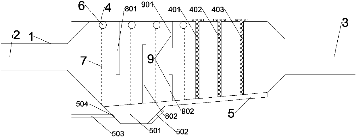
[0030] A straight-through gas purification device, comprising a purifier body 1, an air inlet 2 and an exhaust port 3 are respectively provided at both ends of the purifier body 1, and it is characterized in that an upper end outside of the purifier body 1 is provided with There is a water inlet channel 4, and the inside of the upper end of the purifier body 1 is provided with a nozzle 6 communicating with the water inlet channel 4, and a row of regularly distributed water outlet holes is provided under the nozzle 6, and the inside of the purifier body 1 There are three baffles, namely the first baffle 801, the second baffle 802 and the third baffle 9, and the first baffle 801 is fixed on the inner wall of the purifier body 1. There is a passage for ventilation between the upper part and the lower part of the inner wall of the purifier body 1, and the second baffle plate 802 is fixed on the lower part of the inner wall of the purifier body 1 and is left for ventilation with the...

Embodiment 2

[0033]This embodiment is further optimized on the basis of Embodiment 1. Specifically, two rows of regularly distributed water outlet holes are opened below the nozzle 6, and the number of filter layers is set to three, which are respectively the first filter layer 401, the second filter layer 402 and the third filter layer 403, the pore size of the first filter layer 401 is larger than the pore size of the second filter layer 402, the pore size of the second filter layer 402 is larger than the pore size of the third filter layer 403, the The first baffle 801, the second baffle 802, the third baffle 9, the first filter layer 401, the second filter layer 402 and the third filter layer 403 are distributed in sequence along the direction from the air inlet 2 to the exhaust port 3. The inside of the purifier body 1, and the first filter layer 401, the second filter layer 402 and the third filter layer 403 are connected with the purifier body 1 through a chute, and the drainage groo...


PUM


Abstract

The invention discloses a straight-through gas purification device, and relates to the technical field of gas purification. The problems that an existing gas purification apparatus is complicated in structure and is poor in purification effect are solved. The straight-through gas purification device comprises a purifier body, wherein two ends of the purifier body are provided with a gas inlet anda gas outlet respectively. The straight-through gas purification device is characterized in that the outer side of the upper end of the purifier body is provided with a water inlet passage; the innerside of the upper end of the purifier body is provided with spray pipes communicated with the water inlet passage; the interior of the purifier body is provided with baffle plates; the interior of thepurifier body is provided with filter layers; the lower end surface of the purifier body is provided with a water drainage channel used for collecting wastewater. The straight-through gas purification device has the advantages of being simple in structure, wide in scope of application, good in purification effect and free from noise.

Description

technical field [0001] The invention relates to the technical field of gas purification equipment, in particular to a straight-through gas purification device. Background technique [0002] With the development of economy and society, the automobile industry is developing rapidly, and the exhaust gas produced by automobiles in operation is an important source of urban air pollution. Particulate matter (PM) in vehicle exhaust is one of the most important pollution sources that constitute urban smog. The composition of particulate matter in automobile exhaust is complex and has strong adsorption capacity, which can adsorb various metal dust, strong carcinogen benzopyrene and pathogenic microorganisms. Automobile exhaust particles enter the lungs of the human body with breathing, and stay in different parts of the respiratory tract through collision, diffusion, deposition, etc., causing respiratory diseases. When the suspended particles accumulate to a critical concentration, ...

Claims


Application Information

Patent Timeline
Patent Type & Authority Applications(China)
IPC IPC(8): B01D50/00
CPCB01D50/10
Inventor 孙元伟
Owner CHENGDU KECHUANGGU TECH CO LTD
Learn More