
Powder cylinder cleaner

A washing machine and powder cartridge technology, which is applied in the field of powder cartridge washing machines, powder containers for construction and construction, to improve the cleaning effect, and can solve the problems of poor cleaning effect and achieve good cleaning effect, good cleaning effect and good mixing effect Effect

Inactive Publication Date: 2018-03-16
李秀青
View PDF1 Cites 0 Cited by
  • Summary
  • Abstract
  • Description
  • Claims
  • Application Information

AI Technical Summary

Problems solved by technology

[0005] The purpose of the present invention is to overcome the defects and problems of poor cleaning effect in the prior art, and provide a powder cartridge cleaning machine with better cleaning effect

Method used


Image

  • Powder cylinder cleaner
  • Powder cylinder cleaner

Examples


Embodiment Construction

[0026] The present invention will be described in further detail below in conjunction with the accompanying drawings and specific embodiments.

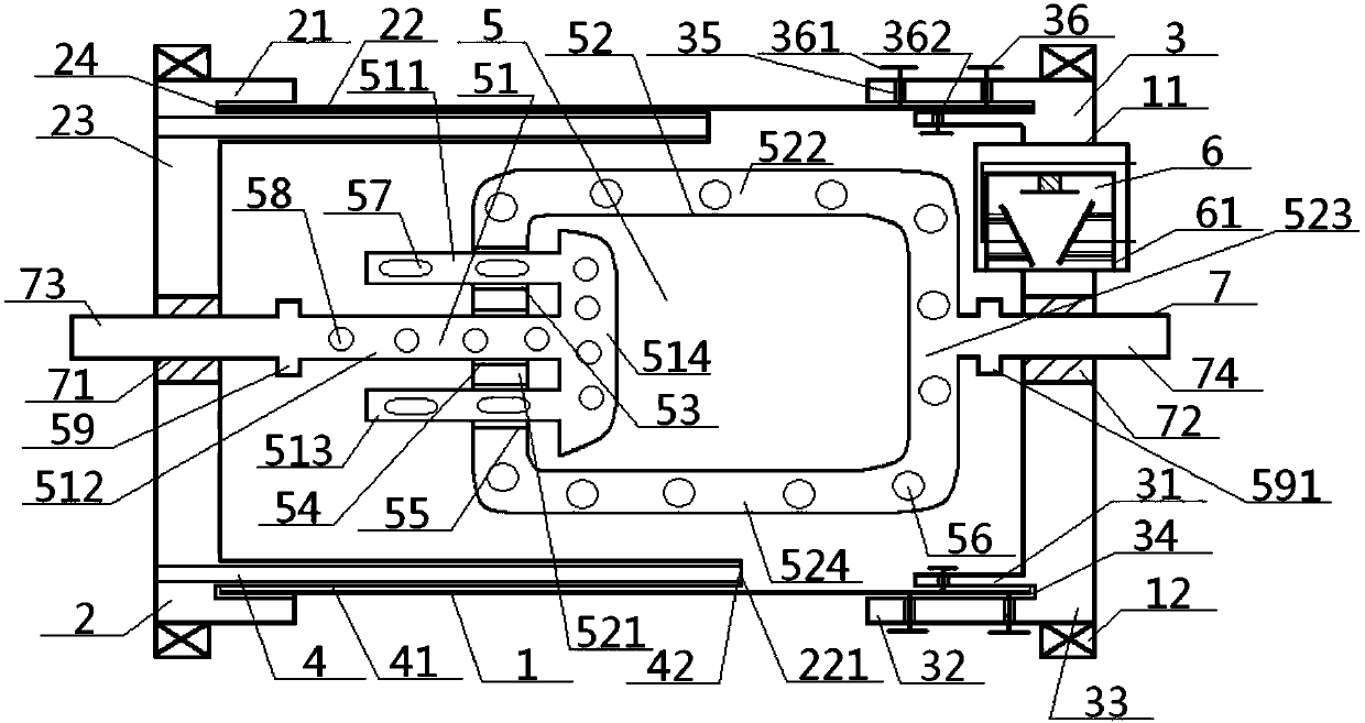
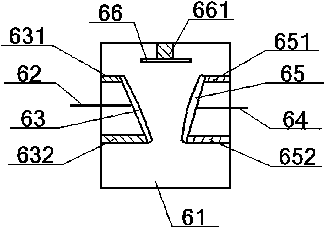
[0027] see Figure 1 to Figure 2 , a powder cartridge cleaning machine, comprising a powder-loading cylinder 1, a wall-cleaning assembly 5 and a wall-cleaning rotating shaft 7, the inside of the powder-loading cylinder 1 is provided with a wall-cleaning assembly 5, the wall-cleaning assembly 5 The interior is connected to the middle part of the wall cleaning shaft 7, and the left and right ends of the wall cleaning shaft 7 extend to the outside of the powder loading cylinder 1 after passing through the left and right ends of the powder loading cylinder 1;

[0028] The left and right ends of the wall-cleaning rotating shaft 7 are respectively connected with the left bearing 71 and the right bearing 72, and the left bearing 71 and the right bearing 72 are respectively located in the middle of the heating end plate 2 and the power end pl...


PUM


Abstract

The invention discloses a powder cylinder cleaner. A left driving shaft in the powder cylinder cleaner drives a left upper pipe, a left middle pipe, a left lower pipe and a left vertical pipe to rotate and move back and forth; a right driving shaft drives a right left vertical pipe, a right upper transverse pipe, a right right vertical pipe and a right lower transverse pipe to rotate and move backand forth; a right exhaust hole, a left transverse air hole and a left circular air hole can outwards spray gas to form eddy currents or feed medicines for cleaning online; a heating device arrangedon a heating end disc can be used for heating; and a temperature measuring sensor arranged on a power end disc can monitor the temperature in a powder charging cylinder. The powder cylinder cleaner isbetter in stirring effect and more uniform in heating and cleaning function, and can feed the cleaning medicines online to achieve better cleaning effect.

Description

technical field [0001] The invention relates to a powder container for building construction, which belongs to the field of construction, in particular to a powder cylinder cleaning machine, which is particularly suitable for improving the cleaning effect. Background technique [0002] At present, sand, slurry, powder, and granular materials are commonly used materials in construction. During transportation, storage, or use, various types of tanks are required, and after use, corresponding The tank body is cleaned to avoid affecting the next use or reducing the service life of the tank body. [0003] The authorized announcement number is CN203865299U, and the authorized announcement date is October 8, 2014. The invention patent discloses a storage and supply tank, including a tank body, a feed port, a feed pipe, a feed pipe discharge port, and legs. The outlet of the storage tank also includes a quantitative feeding valve and a bulk air collecting device. Although this des...

Claims


Application Information

Patent Timeline
Patent Type & Authority Applications(China)
IPC IPC(8): B08B9/08G01K13/00
CPCG01K13/00B08B9/0804
Inventor 李秀青
Owner 李秀青
Learn More