Crank case air impermeability testing table and operating method thereof

A test bench and crankcase technology, which is used in fluid tightness testing, fluid tightness measurement using liquid/vacuum, and machine/structural component testing. and other problems to avoid damage to the workpiece, improve detection accuracy, and ensure human safety.

Inactive Publication Date: 2018-03-16
ZHENGZHOUSCEME
5 Cites 2 Cited by

AI-Extracted Technical Summary

Problems solved by technology

[0003] As the power source of compressed air, air compressors are used in all walks of life in machinery manufacturing. As an important part, the crankcase in the air compressor is particularly important for its airtightness. A crankcase with poor airtightness will affect the performance of the air compressor. Due to the stability of the work, the air pressure of the compressed air output by the air compressor cannot re...

Abstract

The invention discloses a crank case air impermeability testing table and an operating method thereof. The crank case air impermeability testing table comprises a testing box, supporting legs, a testing table body, an external plate, a support, an illumination lamp, an installing plate, a pressure meter, a control plate, startup buttons, an air tube, a sliding rail, a pressure plate, a positioningblock, a fixing clamp, a magnetic air valve, a supporting plate, a pressure transmitter and an air cylinder. The crank case air impermeability testing table has the advantages that the supporting legs are installed at the bottom of the testing box through screws and are adjustable in height, and the whole device is adjusted to reach the height suitable for an operator so that the operation can beconvenient and effort can be saved. The illumination lamp is arranged on the support at the upper portion of the testing table body, the lighting demand during detection can be met, two symmetric startup buttons are fixed to the test table body and are serially connected, the pressure plate is started with two hands to act so as to ensure human safety, a plugging device matched with a crank caseis fixed in a fixing clamp, the cavity of the crank case is sealed as much as possible, and accordingly the purpose of improving the detection precision is achieved.

Application Domain

Measurement of fluid loss/gain rate

Technology Topic

EngineeringCrankshaft +4

Image

  • Crank case air impermeability testing table and operating method thereof
  • Crank case air impermeability testing table and operating method thereof

Examples

  • Experimental program(1)

Example Embodiment

[0025] The technical solutions in the embodiments of the present invention will be clearly and completely described below in conjunction with the accompanying drawings in the embodiments of the present invention. Obviously, the described embodiments are only a part of the embodiments of the present invention, rather than all the embodiments. Based on the embodiments of the present invention, all other embodiments obtained by those of ordinary skill in the art without creative work shall fall within the protection scope of the present invention.
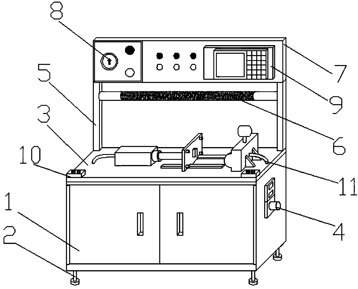
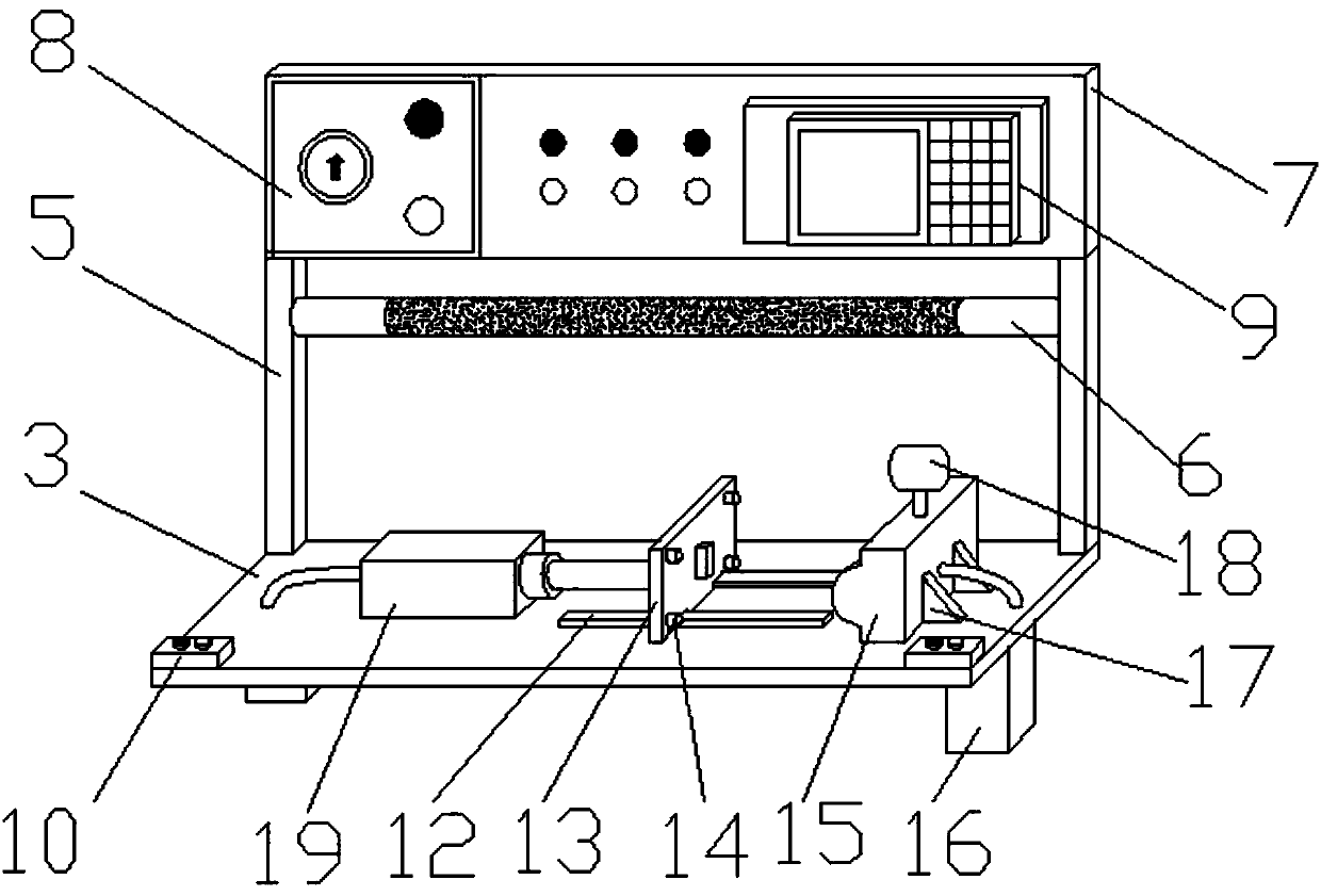
[0026] See Figure 1-2 , A test bench for crankcase air tightness, including test box 1, support foot 2, test bench 3, external board 4, bracket 5, lighting 6, mounting board 7, pressure gauge 8, control board 9, Start button 10, air pipe 11, slide rail 12, pressure plate 13, positioning block 14, fixed clamp 15, solenoid valve 16, support plate 17, pressure transmitter 18 and cylinder 19; the bottom of the test box 1 is provided with a support Foot 2. The supporting foot 2 is mounted on the bottom of the test box 1 by a screw and its height can be adjusted. The upper part of the test box 1 is provided with a test stand 3, and an external board 4 is fixed on the side of the test stand 1. A bracket 5 is fixed on the table 1, a mounting plate 7 is fixed on the top of the bracket 5, a pressure gauge 8 and a control board 9 are fixed on the mounting plate 7, and the pressure gauge 8 and the control board 9 are electrically connected together, so An illuminating lamp 6 is fixed between the two brackets 5, the illuminating lamp 6 and the control board 9 are electrically connected together, a fixing clamp 15 is fixed on the test bench 3, and a pressure is set in the inner cavity of the fixing clamp 15 The transmitter 18, the pressure transmitter 18 and the pressure gauge 8 are electrically connected together, the back of the fixing fixture 15 is provided with a support plate 17, and the support plate 17 is fixed on the test bench 3, and the test bench 3 is fixed with a slide rail 12, the pressure plate 13 is clamped on the slide rail 12, a cylinder 19 is fixed on the test bench 3, the cylinder 19 and the pressure plate 13 are connected together, and the bottom of the test bench 3 A solenoid valve 16 is fixed. The solenoid valve 16 and the control board 9 are electrically connected together. The air cylinder 19 and the fixing clamp 15 are connected to the external board 4 through a gas pipe 11, and the solenoid gas valve 16 is installed on the gas pipe 11. In the middle, a positioning block 14 is fixed on the pressure plate 13 and the fixing fixture 15, two symmetrical start buttons 10 are fixed on the test bench 3, and the two start buttons 10 are connected in series, the start button 10 and the control board 9 Electrically connected, a plugging device matched with the crankcase is fixed inside the fixing clamp 15.
[0027] As a technical optimization solution of the present invention: the supporting foot 2 is installed at the bottom of the test box 1 by a screw and its height is adjustable; the upper bracket 5 of the test bench 3 is provided with a lighting lamp 6; the test bench 3 are fixed with two symmetrical start buttons 10 and two start buttons 10 in series; the pressure plate 13 and the fixing clamp 15 are fixed with a plastic positioning block 14; the fixing clamp 15 is fixed with a crankcase Box matching plugging device; the gas pressure in the inner cavity of the fixed fixture 15 can be measured by a pressure transmitter 18 and displayed by a pressure gauge 8.
[0028] The operating method of the crankcase air tightness test bench consists of the following steps:
[0029] 1). Connect the external air source and power supply to the entire device through the external board 4;
[0030] 2). Manually place the crankcase to be tested in the fixed fixture 15 and pay attention to the opening of the crankcase against the inner wall of the fixed fixture 15 to prevent it. The blocking device fixed inside the fixed fixture 15 will form a fixed void with the crankcase. Cavity
[0031] 3) Turn on the air source and power switch on the control board 9, and observe the parameters on the control board 9 to check whether the air source pressure is normal;
[0032] 4) Adjust the opening and closing degree of the solenoid valve 16 through the control board 9 so that the pressure to the cylinder 19 and the fixed clamp 15 is maintained at 0.5-0.7 MPa when the start button 10 is pressed;
[0033] 5) Press the switches of the two start buttons 10 with both hands. At this time, the pressure plate 13 will move and resist the crankcase to be tested. The sealed cavity formed by the fixed clamp 15 and the crankcase to be tested will be pressurized, and the pressure transmitter 18 The measurement will measure the internal pressure of the sealed cavity and display it through the pressure gauge 8;
[0034] 6) Observe the value of the pressure gauge 8 and judge the sealing performance of the crankcase to be tested and whether it is qualified;
[0035] 7) Loosen the switches of the two start buttons 10 with both hands, the pressure plate 13 will reset to prepare for the next test;
[0036] 8). Remove the tested crankcase from the fixed fixture 15.
[0037] When the present invention is in use, the external air source and power source are first connected to the entire device through the external board, and the crankcase to be tested is manually placed in the fixed fixture. The blocking device fixed inside the fixture will form a single piece with the crankcase. For a fixed cavity, turn on the air source and power switch on the control panel, and observe the parameters on the control panel to check whether the air source pressure is normal. Adjust the opening and closing degree of the solenoid valve through the control panel, so that the opening and closing degree of the solenoid valve is adjusted through the control panel to make it open when the start button is pressed. The pressure to the cylinder and the fixed fixture is maintained at 0.5~0.7MPa, and the two start buttons are pressed with both hands. At this time, the pressure plate will move and resist the crankcase to be tested. The sealed cavity formed by the fixed fixture and the crankcase to be tested will When pressurized, the pressure transmitter will measure the internal pressure of the sealed cavity and display it through the pressure gauge. Observe the value of the pressure gauge and judge the sealing performance of the crankcase to be tested and whether it is qualified. Release the two start buttons with both hands. , The pressure plate will be reset to prepare for the next test, and finally the tested crankcase can be removed from the fixed fixture.
[0038] For those skilled in the art, it is obvious that the present invention is not limited to the details of the foregoing exemplary embodiments, and the present invention can be implemented in other specific forms without departing from the spirit or basic characteristics of the present invention. Therefore, from any point of view, the embodiments should be regarded as exemplary and non-limiting. The scope of the present invention is defined by the appended claims rather than the foregoing description, and therefore it is intended to fall within the claims. All changes within the meaning and scope of equivalent elements of are included in the present invention. Any reference signs in the claims should not be regarded as limiting the claims involved.
[0039] In addition, it should be understood that although this specification is described in accordance with the implementation manners, not each implementation manner only includes an independent technical solution. This narration in the specification is only for clarity, and those skilled in the art should consider the specification as a whole The technical solutions in the embodiments can also be appropriately combined to form other implementations that can be understood by those skilled in the art.

PUM

no PUM

Description & Claims & Application Information

We can also present the details of the Description, Claims and Application information to help users get a comprehensive understanding of the technical details of the patent, such as background art, summary of invention, brief description of drawings, description of embodiments, and other original content. On the other hand, users can also determine the specific scope of protection of the technology through the list of claims; as well as understand the changes in the life cycle of the technology with the presentation of the patent timeline. Login to view more.

Similar technology patents

Movable support of square roller conveyor

PendingCN107161640Aclosely connectedeasy to use
Owner:江苏凯威药用包装有限公司

Oil receiving device for chemical machinery equipment

InactiveCN109966789AEasy to collect oilclosely connected
Owner:QINGDAO BAIJIANCHENG ENVIRONMENTAL PROTECTION TECH CO LTD

Steering engine

InactiveCN108930771Aclosely connectedreduce volume
Owner:北京若唯世纪科技有限公司

Classification and recommendation of technical efficacy words

  • closely connected
  • easy to use

Precast concrete production line

ActiveCN109834814Aclosely connectedFast shipping
Owner:LANGFANG HESS BUILDING MATERIALS MACHINERY CO LTD +1

Laser assisted total joint arthroplasty

InactiveUS20090234360A1easy to use
Owner:ALEXANDER VLADIMIR

Enclosure for a portable hemodialysis system

ActiveUS20090114582A1easy to use
Owner:DEKA PROD LLP
Why Eureka
Try Eureka