Orientation control method for drone

A positioning control and aircraft technology, applied in the field of aircraft, can solve the problems that ultrasonic signals are easily interfered by other signals, calculation method errors, and inaccurate positioning of aircraft 12

Inactive Publication Date: 2018-03-16
BALTEK CO LTD
View PDF10 Cites 10 Cited by
  • Summary
  • Abstract
  • Description
  • Claims
  • Application Information

AI Technical Summary

Problems solved by technology

[0009] However, the ultrasonic signal is easily interfered by other signals, and the directivity of the ultrasonic wave is too strong. If there is an obstacle (such as a human body) between the aircraft 12 and the target device 14, the transmission of the ultrasonic signal will be affected.
Furthermore, the related technology mainly calculates the orientation of the aircraft 12 based on the time difference between the two transceivers 121 and 122 for receiving the ultrasonic signal. Under normal circumstances, such a calculation method will produce considerable errors, resulting in inaccurate positioning of the aircraft 12

Method used


Image

  • Orientation control method for drone
  • Orientation control method for drone
  • Orientation control method for drone

Examples


Embodiment Construction

[0093] A preferred embodiment of the present invention will be described in detail below in conjunction with the drawings.

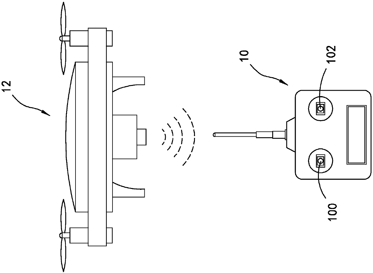
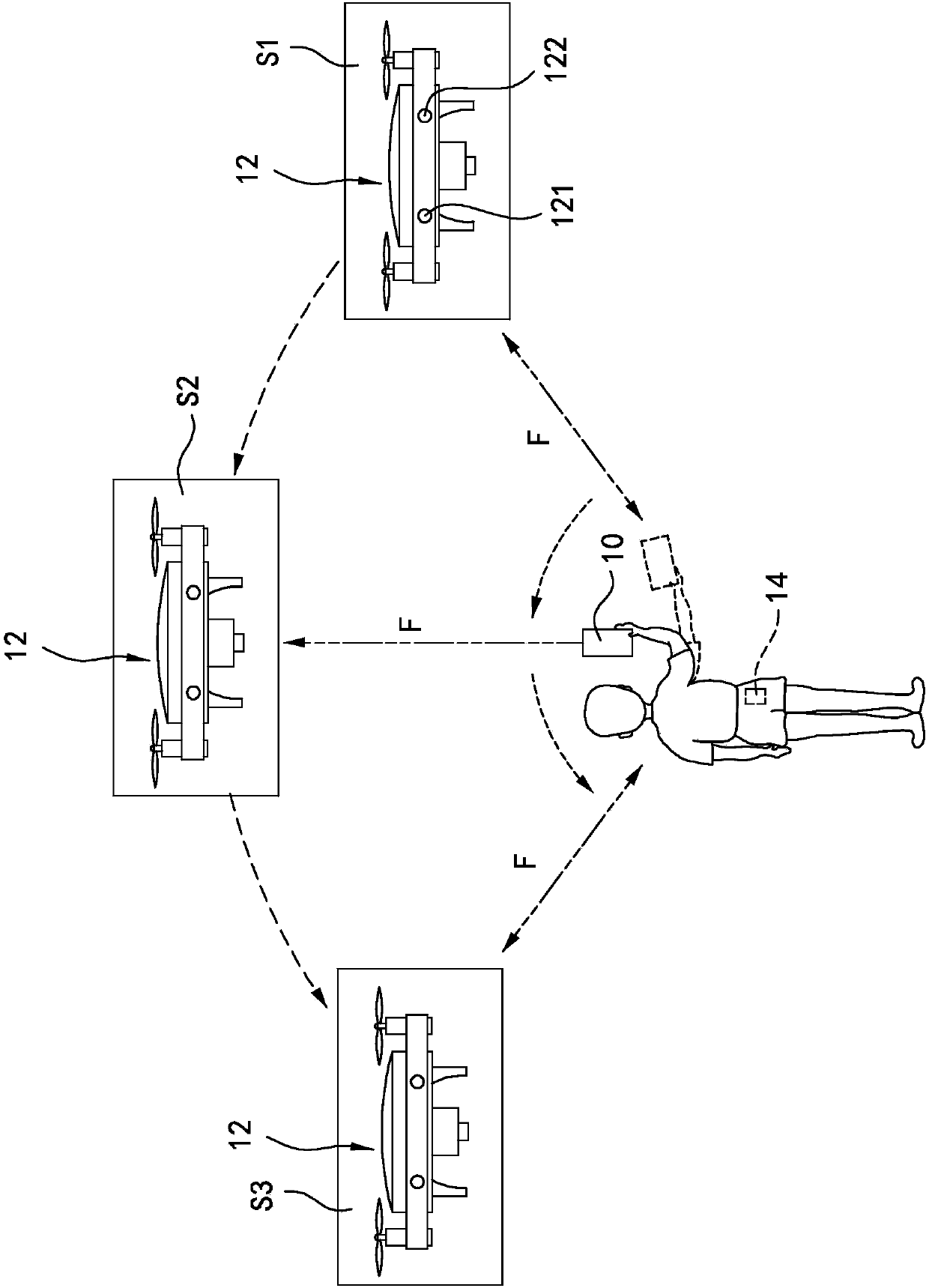
[0094] See first image 3 , is the aircraft system architecture diagram of the first specific embodiment of the present invention. The present invention mainly discloses a positioning control method of an aircraft (hereinafter referred to as the method for short in the specification), which is mainly used in such as image 3 An aircraft system 2 is shown. Specifically, the aircraft system 2 mainly includes an aircraft 3 (such as a steamship, a hot air balloon, a rotorcraft or a wing aircraft, etc.), a remote control device 4 and a target device 5 . Through this method, the user can use the remote control device 4 to perform pointing operations on the aircraft 3 and make the aircraft 3 fly with the target device 5 as the axis origin.

[0095] The aircraft 3 includes a processor 31, a driving device 32, a plurality of transceivers 33, a phase detector 3...


PUM


Abstract

An orientation control method for a drone is disclosed. The method comprises steps of receiving wireless signal sent wirelessly from a target device by at least three receivers arranged on the drone,and detecting the phase of the wireless signal respectively received by each of the three receivers with a phase detector of the drone. Next, the current relative orientation of the drone with respectthe target device is calculated through a phase differences of the three phases of the three receivers. The drone is controlled to move to orientate user-designated direction according to the calculated current relative orientation and a directional signal sent wirelessly from a remote control. Thus, the drone is allowed to be able to correctly face the direction indicated by a user.

Description

technical field [0001] The invention relates to an aircraft, in particular to a positioning control method for the aircraft. Background technique [0002] see figure 1 , is a schematic diagram of a related art aircraft system. Such as figure 1 As shown, an aircraft 12 in the related art is usually controlled by a joystick 100 , 102 on a remote control device 10 . Specifically, the user can operate the joysticks 100, 102 to control the aircraft 12 to move in a specific direction and turn to a specific orientation. [0003] The remote control device 10 is mainly operated with the aircraft 12 as the axial origin, which makes the user's operation unintuitive. Taking selfie with the aircraft 12 as an example, when the aircraft 12 is facing the user, the direction of the aircraft 12 is just opposite to that of the user (the left side of the aircraft 12 is the right side of the user). When the user wants to control the aircraft 12 to move to the user's right, the joystick 100 ...

Claims


Application Information

Patent Timeline
Patent Type & Authority Applications(China)
IPC IPC(8): G01S5/06G05D1/10G01C21/16G08C17/02
CPCG01C21/165G01S5/06G05D1/101G08C17/02B64C39/024G05D1/0033G01S5/0247B64U2201/20G05D1/0016G01C21/18G05D1/0022G05D1/12G06F3/0338G06F3/0346
Inventor 廖子权
Owner BALTEK CO LTD
Why Eureka
Try Eureka