

Corn seed screening device for agricultural breeding
A screening device, corn technology, applied in the direction of filtering, solid separation, drying gas arrangement, etc., can solve the problems of lack of effective drying of corn kernels, unfavorable corn seed storage, and low efficiency of screening, so as to improve the drying effect and screening High efficiency and vibration-promoting effect
- Summary
- Abstract
- Description
- Claims
- Application Information
AI Technical Summary
Problems solved by technology
Method used
Image

Examples
Embodiment Construction
[0020] Below in conjunction with specific embodiment, the technical scheme of this patent is described in further detail:
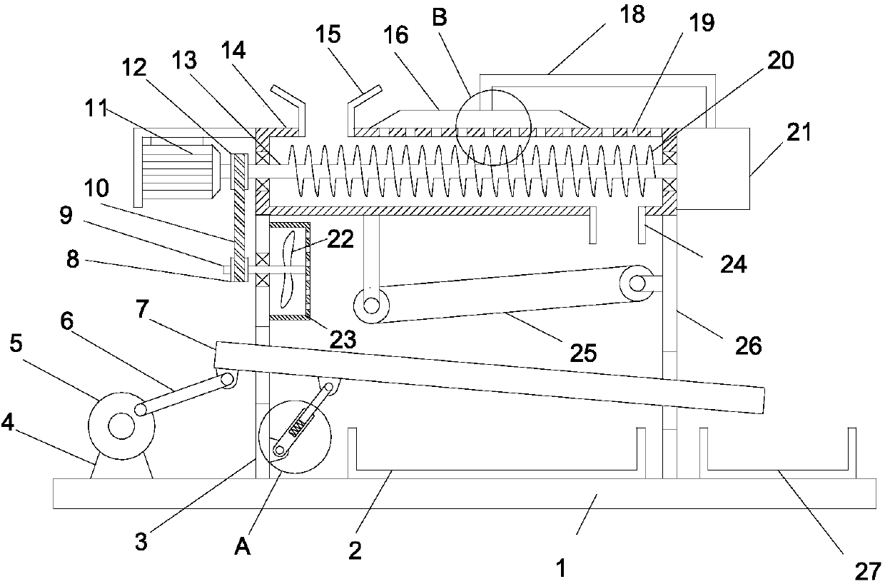
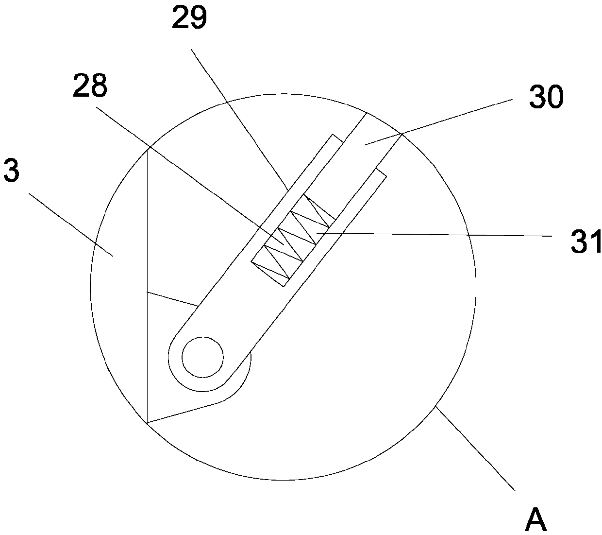
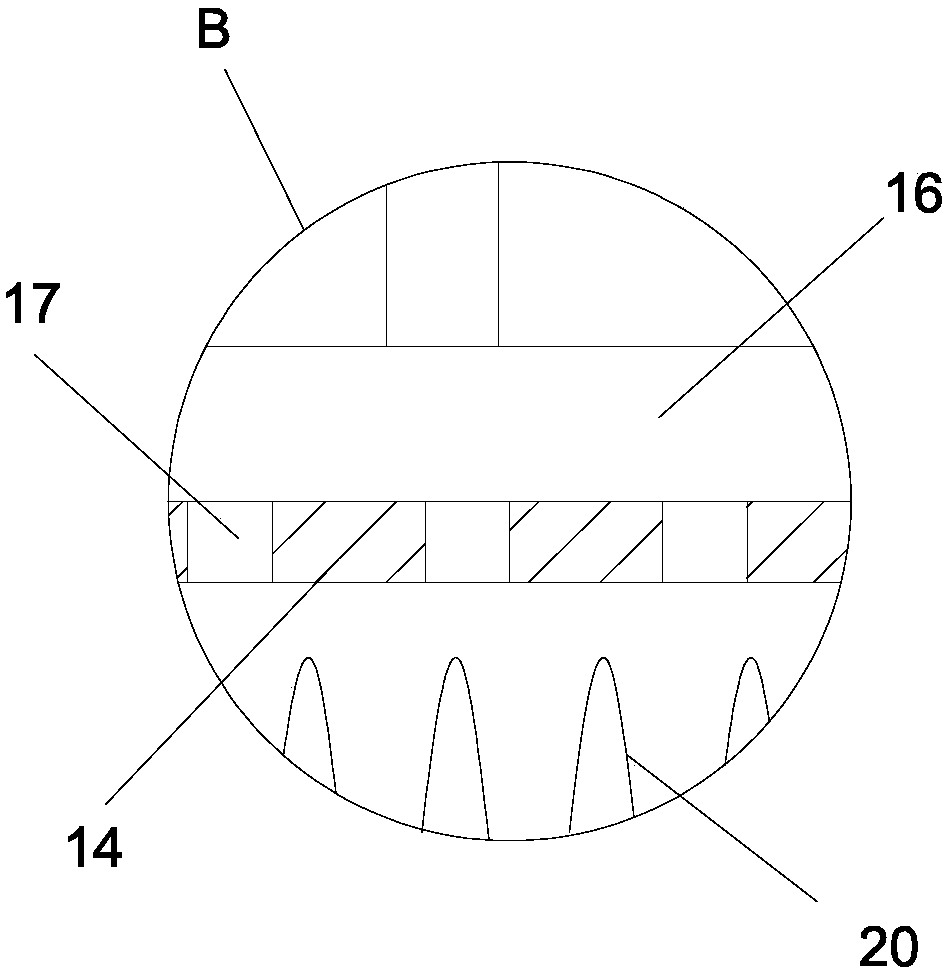
[0021] see Figure 1-4 , a corn seed screening device for agricultural breeding, comprising a base plate 1, a left vertical plate 3 and a right vertical plate 26 are vertically and fixedly installed on the bottom plate 1, and vertically fixedly installed on the left vertical plate 3 and the right vertical plate 26 There is a casing 14, and a driving shaft 13 is installed horizontally in the casing 14. The surface of the driving shaft 13 is fixed with a helical blade 20. The driving shaft 13 extends to the left side of the casing 14, and the driving shaft 13 is covered with The driving pulley 12 is fixedly installed, the left end of the driving shaft 13 is driven and connected to the second motor 11, and the left vertical plate 3 is horizontally rotatably provided with a driven shaft 9, and the driven shaft 9 is sleeved and fixedly installed with a driven ...
PUM
 Abstract
Description
Claims
Application Information