
Bidirectional rotary joint with balance mechanism

A technology of rotary joints and balance mechanisms, which is applied in the fields of manipulators, medical science, and endoscopes, and can solve problems such as difficult to use, large space occupation, and increased size and weight of mechanisms

Pending Publication Date: 2018-03-20
XIANJU XINGZHI TECH CO LTD
View PDF7 Cites 0 Cited by
  • Summary
  • Abstract
  • Description
  • Claims
  • Application Information

AI Technical Summary

Problems solved by technology

In this way, when each rotary joint is in the neutral position, the axes of each section of the rod are not in a straight line, and the entire rod system takes up a lot of space. In some occasions, such as when it is used for medical equipment, it will cause operational obstacles.
In addition, many pipe sections rotate in a vertical plane during use and will be affected by gravity. At present, methods such as weight counterweight and spring balance are used to reduce the influence of gravity. This will inevitably increase the size and weight of the mechanism, and must be miniaturized. Difficult to use with lightweight

Method used


Image

  • Bidirectional rotary joint with balance mechanism
  • Bidirectional rotary joint with balance mechanism
  • Bidirectional rotary joint with balance mechanism

Examples


Embodiment Construction

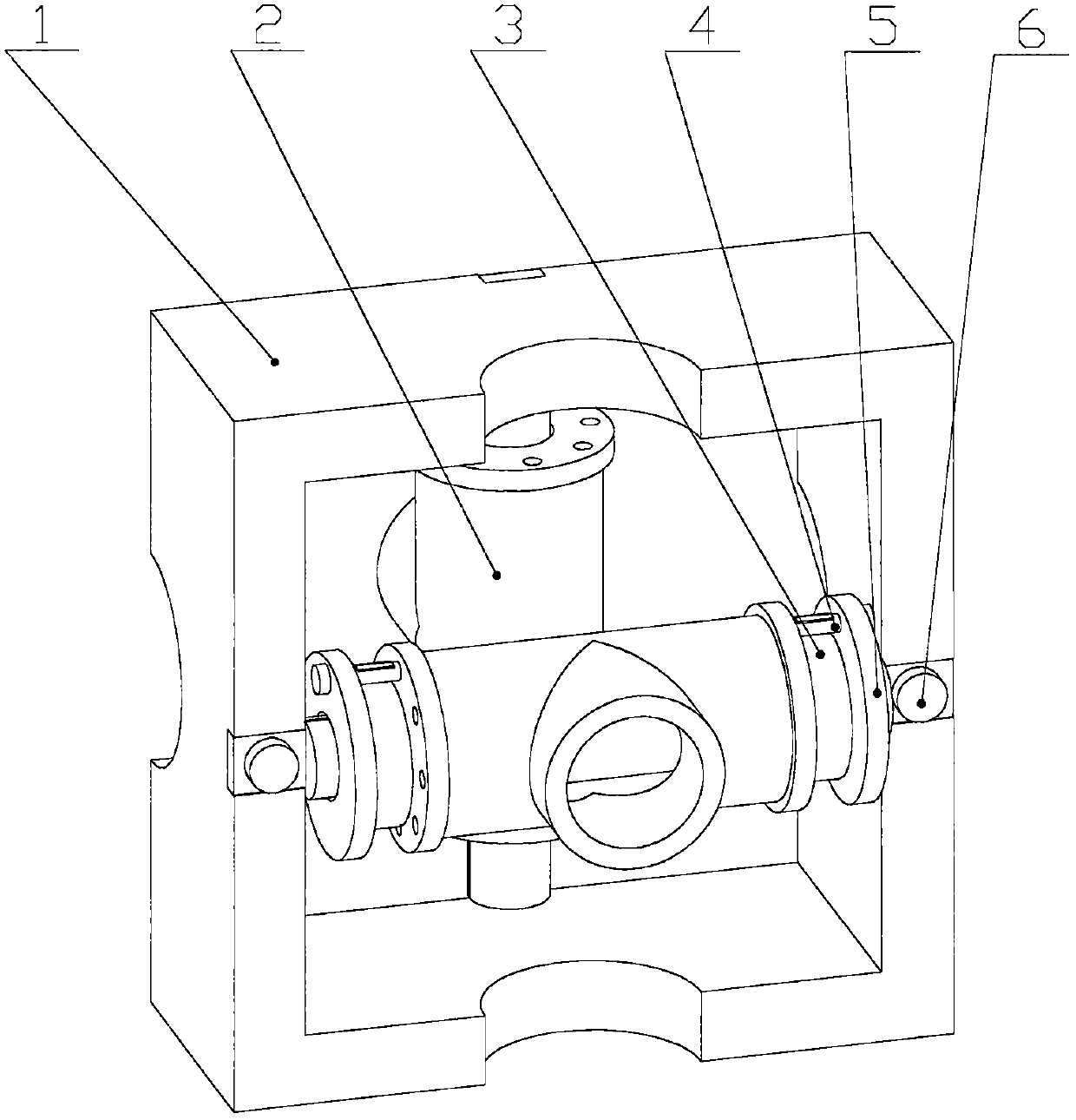
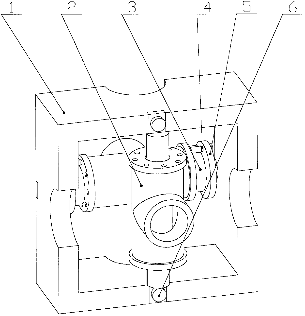
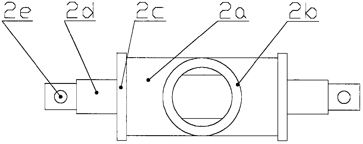
[0018] As shown in the accompanying drawings, the bidirectional rotary joint with a balance mechanism is mainly composed of a bracket, a rotating pair, a spring, etc., and its structure is to have a bracket 1 and two rotating pairs 2; the relative rotation part of the rotating pair 2 is The outer cylinder 2a and the mandrel 2d, there is a connecting rod shaft head 2b outside the outer cylinder 2a; the two ends of the mandrel 2d of the two rotating pairs 2 are respectively fixed on the bracket 1, and the two rotating pairs 2 are in the center When in position, the axes of the connecting rod shaft heads 2b on the two outer cylinders 2a coincide; the main shaft 2d of one or two revolving pairs 2 is covered with the mainspring 3 and the adjusting disc 5 . The details of the structure are: there are screw holes 2e at both ends of the mandrel 2d, and the screws 6 pass through the holes 2e to fix the mandrel 2d on the bracket 1; the two ends of the mandrel 2d also have positioning gro...


PUM


Abstract

The invention discloses a bidirectional rotary joint with a balance mechanism. The bidirectional rotary joint is characterized in that mandrels of two rotation pairs are fixed on a support, and when the two rotating pairs are arranged in middle positions, axes of connecting rod shaft heads on rotatable outer cylinders of the two rotating pairs coincide; and multiple adjusting holes are formed in end covers of the outer cylinders, springs and adjusting plates are arranged on the mandrels in a sleeving mode, inner rings of the springs are fixed in positioning grooves in the mandrels, the adjusting plates can rotate on the mandrels, pin holes are formed in the adjusting plates respectively, pins penetrate through the pin holes respectively, and are inserted into the adjusting holes in the endcovers, and outer rings of the springs fixedly hook on the pins. The bidirectional rotary joint is used in a rod-shaped serial connection mechanism, and rod pieces can do two-way rotary motion; whenthe rotating pairs are in the middle positions, the axes of the front rod piece and the rear rod piece coincide, so that the occupied space of the mechanism is small; when the rotation of the rod pieces need force to balance, torsion of the springs can be conveniently adjusted to provide balance force; and according to the bidirectional rotary joint, the performance of the rod-shaped serial connection mechanism can be remarkably improved, and especially the performance of mechanisms such as an endoscope support and the like can be remarkably improved.

Description

technical field [0001] The invention relates to key components of a rod-shaped series mechanism, in particular to a bidirectional rotary joint with a balance mechanism. Background technique [0002] Rod-shaped series mechanisms are widely used in manipulators, multi-degree-of-freedom position adjustment devices, and end-effector displacement mechanisms. In the multi-section rod-shaped series mechanism, each section has a different rotation direction. At present, the configuration method of multiple rotary joints in series is mostly used. In this way, when all the rotary joints are in the neutral position, the axes of the rods of each section are not in a straight line, and the entire rod system takes up a large space, which may cause operational obstacles in some occasions, such as when used for medical equipment. In addition, many pipe sections rotate in a vertical plane during use and will be affected by gravity. At present, methods such as weight counterweight and spring...

Claims


Application Information

Patent Timeline
IPC IPC(8): B25J17/02B25J19/00A61B1/00
CPCA61B1/00149B25J17/0266B25J19/0016
Inventor 马建群
Owner XIANJU XINGZHI TECH CO LTD
Learn More