Electronic load parallel operation system and method

An electronic load and system implementation technology, applied in the direction of measuring electricity, power supply testing, measuring electrical variables, etc., can solve the problems that the slave machine does not have the ability to work alone and the power expansion capability is limited, so as to ensure the current and increase the expansion power. Effect

Active Publication Date: 2018-03-20
ITECH ELECTRONICS NANJING
View PDF12 Cites 13 Cited by
  • Summary
  • Abstract
  • Description
  • Claims
  • Application Information

AI Technical Summary

Problems solved by technology

[0004] Aiming at the shortcomings of the above-mentioned background technology, the present invention provides an electronic load parallel system and method. By analyzing the parallel signal sent by the master, the slave can not only realize the load synchronization with the master, but also not completely depend on the master to work. Realize the parallel operation of electronic loads, and solve the technical problems that the slave machines do not have the ability to work alone and the power expansion capability is limited in the existing parallel operation scheme

Method used


Image

  • Electronic load parallel operation system and method
  • Electronic load parallel operation system and method
  • Electronic load parallel operation system and method

Examples


Embodiment Construction

[0070] The technical solution of the invention will be described in detail below in conjunction with the accompanying drawings.

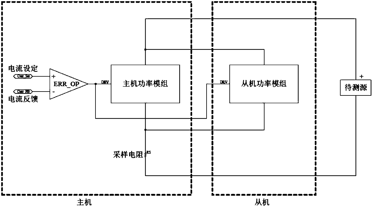
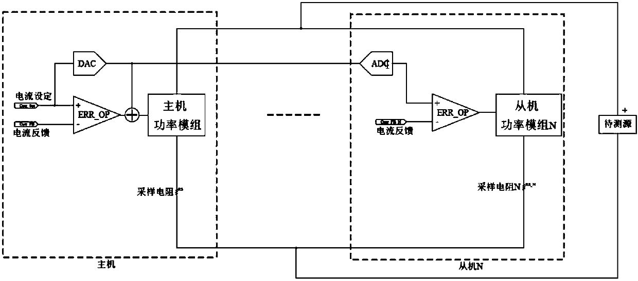
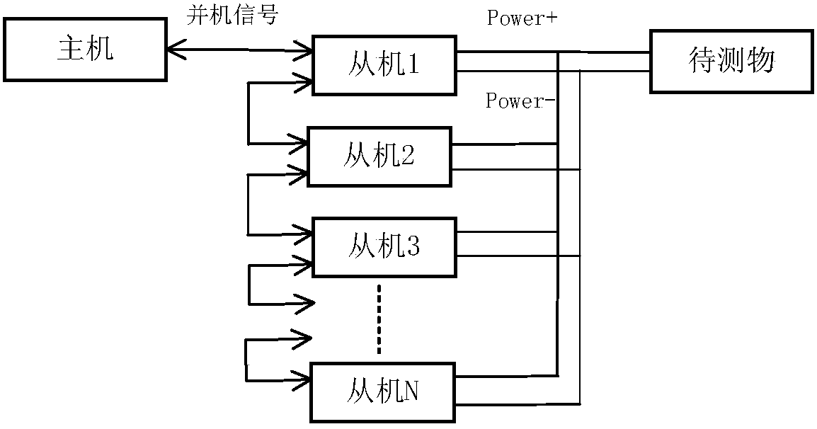
[0071] The electronic load parallel system of the present invention is as image 3 As shown, the electronic load system tests the DUT. The DUT can be a power supply, battery, power supply system, etc. The electronic load system includes a master and multiple slaves. combine Figure 4 to Figure 7 , the host corrects the sink current of the host according to the current setting value to control the main power module to absorb the power on the DUT, and outputs parallel signals including but not limited to drive signals and load synchronization signals in real time according to the current setting value. The slave machine analyzes the current setting value from the parallel machine signal received, and corrects the current drawn by the slave machine according to the current setting value to control the power absorbed by the power module from the DUT. ...


PUM


Abstract

The invention discloses an electronic load parallel operation system and method, and belongs to the technical field of power electronic testing. The electronic load parallel operation system comprisesa host machine and a plurality of slave machines, the host machine performs correction on a current sampling value of an object under test absorbed by a main power module according to a current set value so as to control the main power module and outputs a parallel operation signal containing but not limited to a driving signal and an on-load synchronization signal in real time according to the current set value, and each salve machine receives the parallel signal outputted by the host machine, parses the current set value and performs correction on a current sampling value of the object under test absorbed by a slave power module according to the parsed current set value so as to control the slave power module. The electronic load parallel operation method comprises the steps that the host machine calibrates the current set value to obtain analog voltage representing a parallel operation signal, each slave machine calibrates the analog voltage which is sent by the host machine and represents a parallel operation signal so as to determine the current set value, a host machine calibration coefficient and a slave machine calibration coefficient are combined so as to enable the hostmachine and the slave machine to be consistent in on-load current. The electronic load parallel operation system and method can realize parallel connection of more slave machines so as to increase theextension power.

Description

technical field [0001] The invention discloses an electronic load paralleling system and method, and belongs to the technical field of power electronic testing. Background technique [0002] The electronic load can simulate the load in the real environment, such as electrical appliances, which is a "load" function realized by electronic devices. Specifically, the electronic load controls the conduction of the internal power device MOSFET or transistor to make the power tube dissipate Power, a device that consumes electrical energy. Widely used in LED drive, power module testing, charger production and UPS production and other fields. [0003] At present, electronic loads only realize the working modes of constant voltage, constant current, constant resistance, and constant power in a single machine. With the increasing demand for high power of electronic loads in the market, multiple electronic loads need to be paralleled to share power. Existing load parallel schemes such...

Claims


Application Information

Patent Timeline
Patent Type & Authority Applications(China)
IPC IPC(8): G01R31/00G01R31/40
CPCG01R31/00G01R31/40Y02D10/00
Inventor 马海波其他发明人请求不公开姓名
Owner ITECH ELECTRONICS NANJING
Why Eureka
Try Eureka