Automatic ship tracking method and system based on deep learning network and mean shift

A technology of deep learning network and mean shift, applied in neural learning methods, biological neural network models, character and pattern recognition, etc., can solve problems such as lost targets, error accumulation, poor tracking effect of dynamically changing targets, etc., and achieve good stability sexual effect

Active Publication Date: 2018-03-20
ZHUHAI DAHENGQIN TECH DEV CO LTD
5 Cites 21 Cited by

AI-Extracted Technical Summary

Problems solved by technology

The offline learning method is less effective for dynamically changing target tracking, while the online learning method is pro...

Abstract

The invention relates to an automatic ship tracking method and system based on a deep learning network and mean shift. The method comprises the steps that monitoring video data including coastal areamonitoring video data under visible light are acquired, and each frame of image is extracted; preprocessing is carried out to extract the positive sample and negative sample of a ship target; throughan area-based convolutional neural network method, the samples of the ship target in a video are input into a neural network for model training; the initial frame data of the video are extracted, andship detection and probability density calculation are carried out on initial moment data according to a trained model; and the ship tracking result at the current moment is determined through the calculation result of the previous moment. According to the invention, the method has a great detection result for complex scenes such as clouds, cloudy days, rain and the like; the method has the advantages of high robustness and stability and fully automated tracking process; the stability and accuracy of the neural network method eliminate errors for a mean shift method; and a basis is laid for the tracking of an emerging target.

Application Domain

Technology Topic

Network methodMean-shift +10

Image

  • Automatic ship tracking method and system based on deep learning network and mean shift
  • Automatic ship tracking method and system based on deep learning network and mean shift
  • Automatic ship tracking method and system based on deep learning network and mean shift

Examples

  • Experimental program(1)

Example Embodiment

[0046] In order to better understand the technical solutions of the present invention, the present invention will be further described in detail below with reference to the accompanying drawings and embodiments.
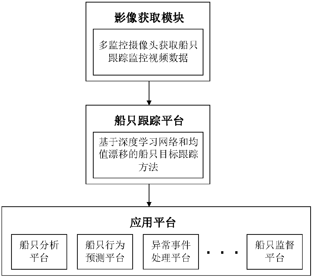
[0047] See figure 1 When the present invention is applied, the applicable system architecture mainly includes a monitoring video acquisition module, a ship tracking platform, and an application platform. The surveillance video acquisition module mainly uses multiple visible light surveillance cameras to acquire the video of the seaside area and download the data to the ship tracking module. The vessel tracking platform adopts the method of the present invention to extract and automatically track the vessel target, and transmit the abnormal situation of the vessel target to the application platform. According to the specific ship analysis platform, behavior prediction platform, abnormal event processing platform, and ship supervision platform in the application platform, the distribution and action analysis of ship targets can be made reasonable predictions and plans to complete related tasks.
[0048] See figure 2 , The method provided by the implementation of the present invention includes the following steps:
[0049] ①Input surveillance video data: the surveillance video data can be collected in advance.
[0050] Monitoring the collection of video data. The data collected by the present invention is mainly monitoring video data of coastal areas under visible light. For the collected video data, each frame of image needs to be obtained through a decoder or code. During specific implementation, collection can be performed in advance.
[0051] ②Data preprocessing and sample preparation: video data preprocessing and ship target positive and negative sample preparation.
[0052] For the acquired surveillance video data, preprocessing is needed to facilitate the subsequent development of digital image algorithms. The preprocessing part mainly uses image smoothing operation, and the present invention uses a median filter method to smooth each frame of video. The positive and negative samples are prepared for the subsequent steps of convolutional neural network training. The specific process is as follows:
[0053] Step 1: Use the video image obtained in step ① to expand the image to a certain extent through rotation, translation, etc. Step 2: Obtain the coordinates of the four vertices of the smallest vertical enclosing rectangle in the remote sensing image for each ship target and the corresponding image, and output the image and all the target coordinates on it as a positive sample. The third step: randomly intercept other areas around the positive sample to obtain the coordinates of the four vertices of the minimum vertical enclosing rectangle, as the negative sample coordinates, and output the image and the negative sample coordinates on it together.
[0054] ③Region-based convolutional neural network training: Through the area-based convolutional neural network method, input the ship target samples in the video into the neural network for model training. The theoretical process is as follows:
[0055] The positive and negative sample data of the ship target completed in step ① is formatted in a standard format, converted into a structured database format, and input into the convolutional neural network for training, and the training result model of the ship target under the surveillance video is obtained. The region-based convolutional neural network consists of multiple alternating convolutional layers, pooling layers, and fully connected layers. It mainly uses backpropagation algorithm (BP algorithm). It has an input layer, multiple hidden layers and an output layer. The formula to express the calculation relationship between the two layers in the BP algorithm is as follows:
[0056]
[0057] Among them, i is the index value of the input layer unit, j is the index value of the hidden layer unit, Represents the weight between the input layer and the hidden layer, Represents the activation bias between each layer, f() represents the activation function of the output layer.
[0058] For the convolutional layer in the convolutional neural network, the network uses the BP neural network mode to update. In a convolutional layer, the feature map of the previous layer is convolved by a learnable convolution kernel, and then through an activation function, the output feature map can be obtained. The lower-level update algorithm after adding the convolution operation is as follows:
[0059]
[0060] Among them, M j Represents all selection sets of the input layer. Represents the convolution kernel between the input layer i and the hidden layer j, Represents the convolution operation process. Therefore, this formula reflects the operational relationship between layer l and layer l-1.
[0061] In addition to the convolutional layer, the convolutional neural network has an important calculation process, that is, the pooling process and the calculation of the pooling layer. The pooling process is a process of aggregation and statistics of features at different positions in a large image. This process greatly reduces feature redundancy and reduces the dimensionality of statistical features. The calculation formula of the pooling layer is as follows:
[0062]
[0063] Among them, D() represents the downsampling function of the pooling process, with To set different activation biases, each bias corresponds to each output layer.
[0064] ④ Extract the initial frame data of the video and calculate the detection result and probability density at the initial moment: Input the video data, and perform ship detection and probability density calculation on the initial moment data.
[0065] a. Use the model trained in step ② to perform ship detection at the initial time in the video data, and obtain the ship detection position at the initial time as the initial position for tracking. And number each ship target.
[0066] b, Based on the mean shift method, calculate each ship at the initial time t 0 Probability density, as attached image 3 The result of the first input. Suppose the target contains n pixels, then {z i } i=1...n Represents the position of each pixel, and divides the gray-scale color space of the area where the target is located to obtain a gray-scale histogram composed of m (m=16) equal intervals. Calculate the initial value of its probability density The formula is as follows:
[0067]
[0068]
[0069]
[0070] among them, Indicates that the center point of the ship (x 0 ,y 0 ) Is set as the normalized pixel position of the origin, x i Indicates position z i The abscissa of the pixel at y i Indicates position z i The vertical coordinate of the pixel at, K uses the Epanechikov kernel function, C represents the normalization coefficient, b(z i ) Means position z i The histogram interval where the pixel at is located, r={1,...,m} is the color interval unit index of the histogram, δ[b(z i )-r] function to determine the pixel z in the target area i Whether the gray value at belongs to the r-th histogram interval unit in the histogram, it is taken as 1, otherwise it is 0.
[0071] ⑤Extract the subsequent frame data to be processed, and determine the ship tracking result of the current frame by the recursive method: set the previous moment as time t-1 and the current moment as time t, and determine the ship tracking result at time t through the calculation result at time t-1, It can record and store the location and evaluation of ships. The process is attached image 3 As shown, the detailed process is as follows:
[0072] A. Enter the tracking result at time t-1, and calculate the probability density of the target position at time t-1 on the image at time t: Take the ξ ship positions tracked at time t-1 as the initial position, and the position of each ship Center coordinate f 0 As the initial target position for ship tracking at time t, let f 0 In order to search the center of the window, get the center position coordinate f of the corresponding candidate ship, use the calculation formula in step b of ④ to calculate the area histogram of the candidate position, and further calculate its probability density, as follows:
[0073]
[0074] Among them, d is the kernel function window size (in this embodiment, for the ship width of the ship data, d=16 is fixedly set).
[0075] B. Calculate the Bhattacharyya coefficient, calculate the result of the mean shift iterative equation, and obtain the mean shift tracking position: the Bhattacharyya coefficient (Bhattacharyya coefficient) is used to determine the difference between the probability density of the vessel tracking position at t-1 and the probability density of the candidate vessel position Description of similarity, according to Taylor expansion formula, the iterative equation for calculating the mean shift of the center of the region is as follows:
[0076]
[0077]
[0078] Among them, K'(x) is the inverse of the K function obtained when the abscissa of the input position is x, w i It is the intermediate process of calculation.
[0079] As the above formula, the whole mean shift method is to iterate from f k (The center position of the kth iteration) Find f k+1 (Iterate the center position of the k+1th time) process, make the model continue to move toward the direction of the largest color change, until the last two moving distances are less than the threshold (this patent uses a threshold of 10 -6 ), that is, the ship position Boxm obtained by finding the mean drift result at time t t. The schematic diagram of the entire mean shift process is attached Figure 4 , With the iterative process, the initial value of the target center position in the figure Move a little bit towards the cluster center, and move to the position after the first iteration Move to position after the nth iteration For multiple (ξ) ship positions tracked at time t-1, the corresponding ship position Boxm is finally obtained through the mean shift method. t. id={1,...,ξ} is the number of multiple mean drift results at time t, and the id-th ship position is expressed as
[0080] C. Extract the detection result of the neural network method at time t, calculate the overlap between the tracking position and the detection result, and exclude the tracking result with a small overlap with the detection result according to the threshold: through the region-based convolutional neural network method and the previously trained ship Model, the ship detection is performed on the image at time t (the image is input in the convolution-based neural network). This method independently obtains the detection result of the image at time t, that is, the detected μ candidate ship positions Boxd t. Let num be the detection result number at time t, num={1,...,μ} detection coordinates for Calculate it and the id The calculation formula for the degree of overlap is as follows:
[0081]
[0082] Among them, S represents the area size, the formula is with The result of dividing the area of ​​the intersection area by the area of ​​the union of the two. Record each With the largest overlap The calculated overlap degree O max If O max Less than the threshold θ 1 (This embodiment takes θ 1 =0.8), the ship’s position is considered to be a false alarm, delete
[0083] That is, for ξ ships at t-1, how many mean drift results will be calculated, id=1,...,ξ; detection will get μ detection results, num=1,...,μ; for each detection result Calculate the value of O. If the detection result does not match the O of any mean drift result greater than the threshold, it is considered a false alarm. If there is a greater than the threshold, the detection result is considered to be the coordinates of a ship, and the result is retained.
[0084] D. Add the detected new target according to the threshold, and output the tracking confirmation result and the new target position at time t: through the neural network detection result of step C, update the new ship target at time t. For each Calculate it and all steps C reserved The maximum overlap degree obtained respectively, denoted as O' max , The overlap degree calculation method is the same as step C, if O' max 2 (This embodiment takes θ 2 =0.4), the ship target is considered to be a new ship at time t, and it is added to the tracking result at time t to obtain a complete set of tracking results. Ie for each Test results, count all retained Whether it overlaps with it, if it does not overlap, it is a new ship target.
[0085] So far, the specific implementation process of the ship automatic tracking method based on deep learning network and mean shift used in this patent is introduced. During specific implementation, the process provided by the technical solution of the present invention can be automatically run by those skilled in the art using computer software technology, or the corresponding system can be implemented in a modular manner. The embodiment of the present invention also provides an automatic ship tracking system based on a deep learning network and mean drift, including the following modules:
[0086] The first module is used for monitoring video data collection, including collecting monitoring video data of coastal areas under visible light, and extracting each frame of image;
[0087] The second module is used for preprocessing based on the video image obtained by the first module, and extracting positive samples and negative samples of the ship target;
[0088] The third module is used to input the ship target samples in the video into the neural network through the region-based convolutional neural network method for model training;
[0089] The fourth module is used to extract the initial frame data of the video, and perform ship detection and probability density calculation on the initial moment data according to the model trained in the third module;
[0090] The fifth module is used to determine the ship tracking result at the current moment through the calculation result at the previous moment, including the following methods:
[0091] Take the ξ ship positions tracked at time t-1 as the initial position, and set the center coordinates of each ship’s position f 0 As the initial target position for ship tracking at time t, let f 0 To search the center of the window, obtain the center position coordinate f of the corresponding candidate ship, calculate the area histogram of the candidate position, and further calculate the probability density;
[0092] The Bhattacharyya coefficient is used to describe the similarity between the ship model and the candidate ship, and the mean shift iterative equation of the regional center is calculated, so that the model continues to move in the direction of the largest color change until the last two moving distances are less than the corresponding preset threshold, find t The position of the vessel obtained by the mean drift result at time, set to obtain multiple vessel positions Boxm t , The id-th vessel position is expressed as
[0093] Through the region-based convolutional neural network method, the image at time t is used for ship detection, and the numth detection coordinates of multiple ships in the image at time t are obtained. for Calculate its position with the id-th vessel Overlap, record each With the largest overlap Corresponding degree of overlap O max If O max Less than the corresponding threshold θ 1 , The ship’s position is considered a false alarm, delete
[0094] Through the detection results of the neural network, the new ship targets appearing at time t are updated, including for each Calculate its sum all The maximum value of the overlap degree obtained respectively O' max If O' max Less than the corresponding threshold θ 2 , It is considered that the ship target is the ship that appears at time t, and it is added to the tracking result at time t to obtain a complete set of tracking results.
[0095] For the specific implementation of each module, refer to the corresponding steps, which will not be repeated in the present invention.
[0096] The specific examples described herein are merely illustrative of the spirit of the present invention. Those skilled in the art to which the present invention pertains can make various modifications or additions to the specific examples described or use similar alternatives, but they will not deviate from the spirit of the present invention or go beyond what is defined in the appended claims. range.

PUM

no PUM

Description & Claims & Application Information

We can also present the details of the Description, Claims and Application information to help users get a comprehensive understanding of the technical details of the patent, such as background art, summary of invention, brief description of drawings, description of embodiments, and other original content. On the other hand, users can also determine the specific scope of protection of the technology through the list of claims; as well as understand the changes in the life cycle of the technology with the presentation of the patent timeline. Login to view more.

Similar technology patents

Preparation method of biocompatible aqueous phase quantum point

Owner:SHANGHAI INST OF TECHNICAL PHYSICS - CHINESE ACAD OF SCI

Preparation of polyurethane curing agent with low free toluene diisocyanate

InactiveCN1424345ALow viscosityGood stabilitySolventHydrocarbons.aliphatic
Owner:SHENZHEN FEIYANG IND CO LTD

Classification and recommendation of technical efficacy words

  • Good stability

Method for preparing Nano silver piece

InactiveCN1958197AHigh purityGood stabilitySURFACTANT BLENDInorganic chemistry
Owner:CHANGCHUN INST OF APPLIED CHEMISTRY - CHINESE ACAD OF SCI

Amorphous irox film ph sensor

Owner:BOARD OF RGT THE UNIV OF TEXAS SYST
Why Eureka
Try Eureka