Control method of public electronic equipment charging system

A technology of electronic equipment and charging system, which is applied in the field of public electronic equipment charging system control, can solve the problems of people guarding and identification of mobile phone users, so as to improve flexibility and convenience, save equipment cost, and realize intelligent access Effect

Inactive Publication Date: 2018-03-20
CHENGDU EXPERT OF BATTERY DESIGN TECH CO LTD
View PDF3 Cites 0 Cited by
  • Summary
  • Abstract
  • Description
  • Claims
  • Application Information

AI Technical Summary

Problems solved by technology

[0004] The purpose of the present invention is to provide a control method for a public electronic equipment charging system to solve the problem of charging mobile phones or other electronic equipment when people go out, and solve the problem that people need to be guarded when charging electronic equipment. It solves the problem of centralized management of charging of electronic equipment, solves the problem of intelligent access to electronic equipment; solves the problem of identification of mobile phone users when charging

Method used


Image

  • Control method of public electronic equipment charging system
  • Control method of public electronic equipment charging system
  • Control method of public electronic equipment charging system

Examples


Embodiment 1

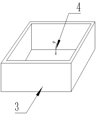
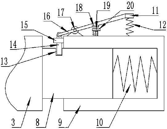
[0042] On the basis of the above embodiments, the present invention also discloses a preferred solution of a charging system for public electronic equipment. The drawer locking mechanism includes a fixed rod 8, which is fixedly connected to the drawer 3, and the charging grid 2 is provided with When the fixed seat 9 and the fixed rod 8 move with the drawer 3 in the charging compartment 2, the fixed rod 8 can be inserted into the fixed seat 9, and a drawer return spring 10 is arranged between the fixed seat 9 and the fixed rod 8.

[0043] Further, a lock hole 13 for locking the drawer 3 is provided on the side of the fixed rod 8, a deadbolt guide ring 15 is arranged on the fixed seat 9, a deadbolt 14 is sleeved in the deadbolt guide ring 15, and the deadbolt 14 It can move linearly in the lock tongue guide ring 15, and the lock tongue 14 can be inserted into the lock hole 13 or pulled out from the lock hole 13 when it moves.

[0044] Further, the fixed seat 9 is provided with a...

Embodiment 2

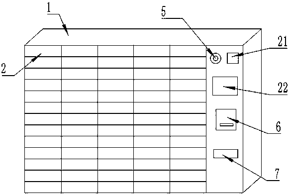
[0051] On the basis of Embodiment 1, the control circuit includes a central control unit, and the central control unit is signal-connected with the fingerprint reader 21, the touch display screen 22, the charging button 5, the barcode printer 6 and the barcode scanner 7 through a communication interface; The electromagnet switch circuit is electrically connected with the central control unit through the electromagnet drive circuit.

[0052] When the device is working, the fingerprint reader 21, the touch display screen 22, the charging button 5, and the barcode scanner 7 transmit the information to the central control unit through the communication interface, and the central control unit transmits the information to the barcode printer 6 through the communication interface after processing 1. The electromagnet driving circuit; the printer 6 prints out the required bar code; the electromagnet driving circuit controls the opening and closing of the electromagnet switch circuit, a...

Embodiment 3

[0054] On the basis of Embodiment 2, the control circuit includes a charging circuit, and the charging circuit is electrically connected to the charging line 4 through a cable; the interface of the charging line 4 includes a Micro USB interface, a USB Type C interface and a Lightning interface. The charging circuit can provide electric energy for electronic devices. Micro USB interface, USB Type C interface and Lightning interface include most of the charging interface ports of electronic equipment on the market, which greatly improves the scope of services. The charging connector is replaced according to the change of the interface.


PUM


Abstract

The invention discloses a control method of a public electronic equipment charging system. The charging system includes a charging cabinet for storing electronic equipment, a plurality of charging grids are arranged on the charging cabinet and internally and movably connected with drawers for placing the electronic equipment, and the drawers are internally provided with charging wires; the drawersare in movable / locked connection with the charging grids through drawer locking mechanisms, and each drawer locking mechanism comprises an electromagnet; a charging device comprises a control circuit, and the electromagnets are electrically connected to the control circuit through cables; the charging cabinet is provided with a fingerprint identifier and a touch display screen which are in signalconnection with the control circuit through cables. By means of the method, people can conveniently charge the electronic equipment in public places where charging is inconvenient, when people chargethe electronic equipment, they do not need to stay beside the charging system, after charging is completed, people can input fingerprints for identification through the fingerprint identifier and input identification codes are identified to achieve the intelligent storage and pickup of the electronic equipment, and the storage and pickup of the electronic equipment are flexible and convenient.

Description

technical field [0001] The invention relates to a charging device, in particular to a method for controlling a charging system of a public electronic device. Background technique [0002] With the popularization of electronic devices, smart phones have become an indispensable part of people's lives, but with more and more functions of smart phones and continuous enhancement of performance, the normal use time of mobile phones is getting shorter and shorter , causing the device to need to be charged frequently, but when people go shopping or playing, they often encounter the problem that the battery of the mobile phone is exhausted and cannot be used, causing great inconvenience. [0003] In the existing technology, a power bank is usually used for emergency charging, but the power bank is bulky, heavy, inconvenient to carry, and needs to be charged, which is very troublesome. Therefore, it is extremely urgent to solve the problem of charging electronic devices outdoors. C...

Claims


Application Information

Patent Timeline
Patent Type & Authority Applications(China)
IPC IPC(8): G07F15/00H02J7/00
CPCG07F15/006H02J7/0044Y02B40/00Y02T90/12
Inventor 代炎利邓佳
Owner CHENGDU EXPERT OF BATTERY DESIGN TECH CO LTD
Why Eureka
Try Eureka