
Transmission box sealing structure of wire drawing machine

A sealing structure and transmission box technology, which is applied to the sealing of engines, transmission parts, mechanical equipment, etc., can solve problems such as inability to guarantee normal production, affect the operation and production efficiency of the wire drawing machine, and reduce the lubrication performance of the transmission box.

Pending Publication Date: 2018-03-23
JIANGSU HONTA MACHINERY
View PDF0 Cites 0 Cited by
  • Summary
  • Abstract
  • Description
  • Claims
  • Application Information

AI Technical Summary

Problems solved by technology

The transmission part of the drawing wheel works in the transmission box of the wire drawing machine, and the drawing wheel shaft is driven to rotate through the gear pair. The drawing wheel shaft passes through the side wall of the transmission box and hangs to the drawing chamber outside the transmission box. The drawing wheel is installed on the overhanging end of the drawing wheel shaft. , driven by the drawing wheel shaft, since the lubricating oil in the transmission box and the drawing oil in the drawing chamber are completely different in nature, they cannot be used together. In this way, the structure of the drawing wheel shaft passing through the wall of the transmission box must ensure that the lubricating oil in the transmission box and the drawing oil The wire drawing oil in the cavity is absolutely isolated, otherwise the mutual leakage between the lubricating oil and the wire drawing oil will reduce the lubrication performance of the transmission box, and the heat dissipation of the wire rod in the wire drawing chamber will be poor, resulting in equipment damage and a decline in the quality of the wire rod, which cannot guarantee normal production
The usual sealing structure can ensure the sealing requirements of ordinary machinery, but in special occasions such as wire drawing machines, especially in the case of large flow direct spray lubrication, the existing general sealing device cannot guarantee the sealing effect, which seriously affects The normal operation and production efficiency of the wire drawing machine

Method used


Image

  • Transmission box sealing structure of wire drawing machine
  • Transmission box sealing structure of wire drawing machine

Examples


Embodiment Construction

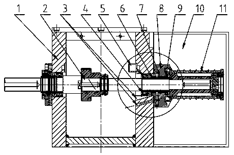
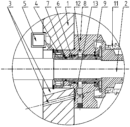
[0016] exist figure 1 In the sealing structure of the transmission box of the wire drawing machine shown, the transmission box 1 is a long box member, and a number of wire drawing axles 2 are rotatably supported on the transmission box 1. Each wire drawing axle 2 is arranged along the length direction of the transmission box 1. The wire drawing drive motor is driven to rotate by a gear pair, the gear pair is located in the transmission box 1, the wire drawing axle 2 passes through the side wall of the transmission box 1 and is rotatably supported on the transmission box 1 by the bearing 4, and the extended end of the wire drawing axle 2 is located in the wire drawing chamber Inside 10 , the wire drawing chamber 10 is a wire drawing working space in a closed casing, and the wire drawing wheel 11 is installed on the extended end of the wire drawing wheel shaft 2 in the wire drawing chamber 10 . see figure 2 , an oil delivery pipe 5 is installed on the inner wall of the transmi...


PUM


Abstract

The invention discloses a transmission box sealing structure of a wire drawing machine. The transmission box sealing structure comprises a transmission box, a wire drawing wheel shaft, a wire drawingwheel and a wire drawing cavity. The wire drawing wheel shaft penetrates the side wall of the transmission box and is rotationally supported on a transmission box body through a bearing. A sealing isolation sleeve is arranged between the bearing and the wire drawing wheel. The sealing isolation sleeve is fixedly connected with the wire drawing wheel shaft in a sealed manner. A sealing base is further arranged between the bearing and the wire drawing wheel. The sealing base and the transmission box are fixedly connected in a sealed manner. At least two machine oil sealing rings are arranged between the outer circle of the sealing isolation sleeve and an inner hole of the sealing base and are adjacent to the bearing. Machine oil discharging channels are arranged between every two adjacent engine oil sealing rings and between each machine oil sealing ring and the bearing and communicate with an inner cavity of the transmission box in a connected manner. A wire drawing oil sealing ring isfurther arranged between the outer circle of the sealing isolation sleeve and the inner hole of the sealing base, and the wire drawing oil sealing ring is adjacent to the wire drawing wheel. By meansof the transmission box sealing structure of the wire drawing machine, it can be guaranteed that lubricating oil in the transmission box can be subjected to effective sealing and isolating, and mutualseepage of the lubricating oil and wire drawing oil is prevented.

Description

technical field [0001] The invention relates to a mechanical device, in particular to an improvement of the sealing structure of a cable drawing machine. Background technique [0002] Cable wire drawing machine is a kind of mechanical equipment that draws metal wires into required wire and cable core materials with thinner diameter specifications. During the wire drawing process, several wire drawing wheels arranged in sequence operate at different speeds. Each wire drawing wheel The speed increases sequentially from front to back, and the wires to be drawn are wound on each drawing wheel one by one from front to back, and the wires to be drawn are drawn by the drawing wheels and produced under the aperture limit of the drawing die between two adjacent drawing wheels Plastic deformation and gradually thinning. In this process, each drawing wheel needs to provide sufficient traction force, so the transmission parts of each drawing wheel are heavily loaded, and extremely effec...

Claims


Application Information

Patent Timeline
Patent Type & Authority Applications(China)
IPC IPC(8): B21C1/12F16H57/029F16J15/24
CPCF16H57/029F16J15/24B21C1/12F16H2057/02069
Inventor 谭礼春
Owner JIANGSU HONTA MACHINERY
Learn More