Oil well cement paste and horizontal well technical casing cementing process

A technology of oil well cement slurry and technical casing, which is applied in the field of oil well cement slurry and horizontal well technical casing cementing technology, and can solve the problems that the brine concentration cannot be guaranteed, the cementing quality is poor, and the plugging effect is small, etc. To achieve the effect of ensuring brine concentration and production life, good cementing quality and reducing cracks

Active Publication Date: 2020-10-13
四川盐业地质钻井大队
View PDF7 Cites 0 Cited by
  • Summary
  • Abstract
  • Description
  • Claims
  • Application Information

AI Technical Summary

Problems solved by technology

[0002] At present, in the underground mining process of mine salt mines, horizontal well drilling construction is a very important link, especially the cementing quality of productive technical casing, which directly determines the brine concentration and production life of the well group; During the deposition process, there is often the possibility of water filling near the top of the salt layer, and this phenomenon is particularly prominent in old mining areas
When tapping the potential of an old mining area, the probability of well kick and lost circulation is very high when drilling near the top of the salt layer, because it is often associated with the adjacent mined rock salt solution cavity, and well killing or cementing is required; the existing In the casing cementing process of horizontal well technology, cement is usually mixed with clean water, and cement slurry is injected into the annular space between the technical casing and the well wall through the technical casing; however, during the solidification of the cement slurry, more Free water, there are many gaps in the cement body, and the pressure holding and coagulation acceleration cannot be completed, and the setting time is long, the cement slurry is easily eroded by the salt layer and the light salt water near the roof, and the gap with the salt layer is also large, so it cannot be sealed. The brine channel is separated, the cementing quality is poor, the plugging effect is very small, and the salt layer roof is severely permeable, so the brine concentration of the well group can not be guaranteed according to the salt layer dissolution characteristics, which affects the brine concentration and production life of the well group

Method used


Image

  • Oil well cement paste and horizontal well technical casing cementing process

Examples


Embodiment 1

[0014] A kind of oil well cement slurry of this embodiment comprises 1 part of G grade oil well cement, 1.2 parts of saturated brine, 0.02 part of oil well cement expansion agent and 0.002 part of coagulant, according to the ring between the casing and the well wall Empty size, the quality of 1 part of G grade oil well cement is 10 tons, the quality of corresponding 1.2 parts of saturated brine is 12 tons, the quality of 0.02 part of oil well cement expansion agent is 200 kg, and the quality of 0.002 part of coagulant is 20 kg, the oil well cement expansion agent uses montmorillonite, the coagulation accelerator uses calcium chloride, and mixes evenly.

Embodiment 2

[0016] An oil well cement slurry of this embodiment includes 1 part of G grade oil well cement, 1.1 part of saturated brine, 0.018 part of oil well cement expansion agent and 0.0025 part of coagulant. Empty size, the quality of 1 part of G grade oil well cement is 8 tons, the quality of corresponding 1.1 parts of saturated brine is 8.8 tons, the quality of 0.018 part of oil well cement expansion agent is 144 kg, and the quality of 0.0025 part of coagulant is 20 kg, the oil well cement expansion agent uses montmorillonite, the coagulation accelerator uses calcium formate, and mixes evenly.

Embodiment 3

[0018] A kind of oil well cement slurry of this embodiment comprises 1 part of G grade oil well cement, 1.35 parts of saturated brine, 0.03 part of oil well cement expansion agent and 0.003 part of coagulant, according to the ring between casing and well wall Empty size, the quality of 1 part of G grade oil well cement is 20 tons, the quality of corresponding 1.35 parts of saturated brine is 27 tons, the quality of 0.03 part of oil well cement expansion agent is 600 kg, and the quality of 0.003 part of coagulant is 60 kg, the oil well cement expansion agent uses montmorillonite, the coagulation accelerator uses calcium formate, and mixes evenly.

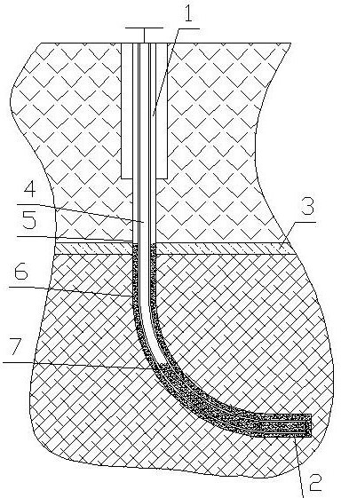
[0019] like figure 1 As shown, the horizontal well technical casing cementing process using any of the above three oil well cement slurries includes the following steps: A) establish a horizontal well 1, and run the technical casing 4 into the wellbore until the level of the horizontal well 1 Section 2, the horizontal section 2 is l...


PUM


Abstract

The invention discloses oil well cement paste. The oil well cement paste comprises 1 part of oil well cement, 1.1 to 1.35 parts of saturated salt water, 0.018 to 0.03 part of oil well cement expandingagent and 0.002 to 0.003 part of coagulation accelerator. The horizontal well intermediate casing cementing process comprises the following steps that: A) a horizontal well is established, and an intermediate casing is installed into the borehole of the horizontal well until reaching the horizontal section of the horizontal well; B) oil well cement paste is injected into an annulus between the intermediate casing and the well wall of the horizontal well, and then first displacement operation is performed so as to make the oil well cement paste enter a salt bed top plate and the annulus between the intermediate casing below the salt bed top plate and the well wall, and part of the oil well cement paste is left in the intermediate casing; when the thixotropy of the cement paste is enhancedbefore the initial setting of the cement paste, second-time displacement operation is conducted, when the initial setting thixotropy of the cement paste is worst, third-time displacement operation isconducted, a part of the oil well cement paste left in the intermediate casing is ejected out every time, and a part of the cement paste is left in the intermediate casing; and C) solidification is performed. According to the method, gaps between the cement and the borehole can be greatly reduced, pressure maintaining and coagulation promoting can be completed, a light salt brine channel can be effectively sealed and isolated, well cementation quality is good, the water permeation of the salt bed top plate is prevented, and the brine concentration and the production life of a well group are guaranteed.

Description

technical field [0001] The invention relates to an oil well cement slurry and a horizontal well technical casing cementing process using the cement slurry. Background technique [0002] At present, in the process of underground mining in mines and salt mines, horizontal well drilling construction is a very important link, especially the cementing quality of productive technical casing, which directly determines the brine concentration and production life of the well group; During the deposition process, there is often the possibility of water filling near the top of the salt layer, and this phenomenon is particularly prominent in old mining areas. When exploiting the potential of old mining areas, the probability of well kick and lost circulation is very high when drilling near the top of the salt layer, because it is often associated with the adjacent mined rock salt solution cavity, and well killing or cementing is required; the existing In the casing cementing process of...

Claims


Application Information

Patent Timeline
IPC IPC(8): C04B28/00C09K8/42C09K8/467E21B33/14
CPCC04B28/00C09K8/422C09K8/467E21B33/14C04B24/04C04B22/124C04B14/04
Inventor 李中峰尹水王长虹刘芬
Owner 四川盐业地质钻井大队
Why Eureka
Try Eureka