Air pressure detection based robot foot structure and pressure detection method

A kind of air pressure detection and robot technology, which is applied in elastic deformation gauge type fluid pressure measurement, fluid pressure measurement, instruments and other directions. It can solve the problems of low measurement accuracy, complicated installation and complicated design, and achieve high measurement accuracy and strong adaptability. , the effect of easy installation

Inactive Publication Date: 2018-03-23
深圳市行者机器人技术有限公司
View PDF13 Cites 7 Cited by
  • Summary
  • Abstract
  • Description
  • Claims
  • Application Information

AI Technical Summary

Problems solved by technology

[0007] 1. Complex installation and complex design;
[0008] 2. Heavy weight and high price;
[0009] 3. The measurement accuracy is low, and the measurement range is not easy to change;
[0010] 4. It is necessary to embed the pressure sensor into the foot structure of the robot, which is difficult to implement modularly

Method used


Image

  • Air pressure detection based robot foot structure and pressure detection method
  • Air pressure detection based robot foot structure and pressure detection method
  • Air pressure detection based robot foot structure and pressure detection method

Examples


Embodiment 1

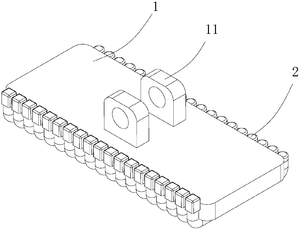
[0045] This embodiment provides a robot foot structure based on air pressure detection, such as figure 1 As shown in -3, it includes a foot plate 1, an air pressure detection unit 2.

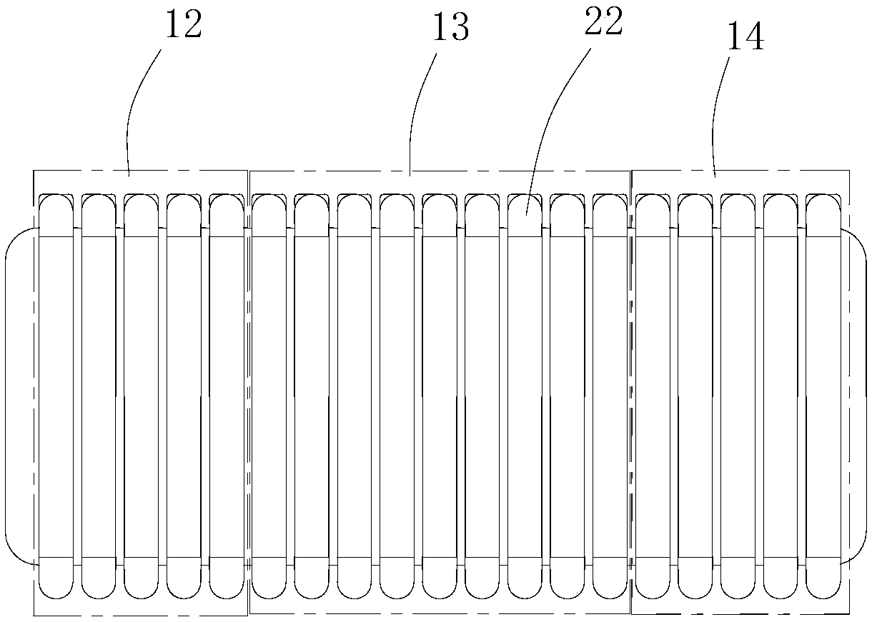
[0046] Among them, the foot plate 1 has a square structure, and a connecting assembly 11 for connecting the legs of the robot is provided above the foot plate 1 to facilitate the modularization of the entire foot structure production and manufacturing process. The entire footboard 1 is divided into a forefoot detection area 12, a midfoot detection area 13, and a backfoot detection area 14.

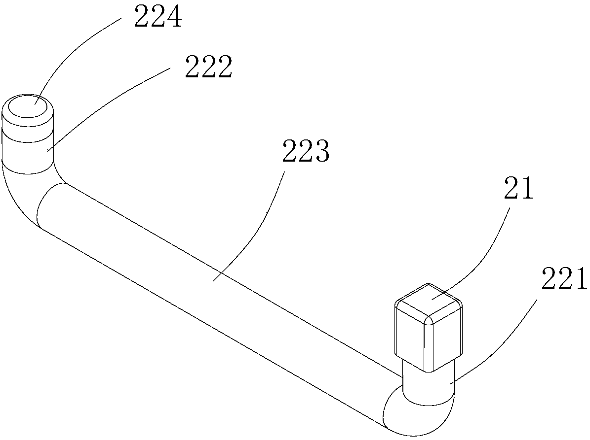
[0047] The air pressure module includes a plurality of air pressure detecting units 2, which include an air pressure sensor 21 and a tubular airbag 22. The tubular airbag 22 in each air pressure monitoring unit 2 is linearly arranged along the front and rear direction of the foot plate 1. An arc-shaped connecting portion (not shown in the figure) is provided at the joint between the foot plate 1 and the tubular a...

Embodiment 2

[0054] This embodiment provides a robot foot structure based on air pressure detection, such as Figure 4 As shown in -5, it includes the foot board 3 and the air pressure monitoring unit 4.

[0055] Among them, the foot plate 3 is a trapezoid-like structure with a modular design, which facilitates the entire production process of the foot structure. The entire footboard 3 is divided into a forefoot detection area 31, a midfoot detection area 32, and a backfoot detection area 33.

[0056] The air pressure module includes a plurality of air pressure detecting units 4, which include an air pressure sensor 41 and a block airbag 42. The block airbag 42 in each air pressure monitoring unit 4 is arranged in an array along the center of the footboard. The connecting part of the foot board 3 and the block airbag is provided with a groove (not shown in the figure), and the block airbag 42 has a structure such as Figure 5 As shown, it includes an airbag body for placing the connecting piec...


PUM


Abstract

The invention provides a foot structure. The foot structure comprises a foot plate, an air pressure module and a data processing module, wherein the air pressure module and the data processing moduleare arranged at the bottom of the foot plate. Connecting assemblies used for being connected with legs of a robot are arranged on the foot plate. The air pressure module comprises at least one air pressure detection unit, and the air pressure detection units are arranged at the bottom of the foot plate. Each air pressure detection unit comprises an air pressure sensor and an air bag, wherein the air pressure sensor is connected with the air bag. Each air bag is provided with an inflation opening. The data processing module is used for acquiring data of contact with the ground so as to adjust the walking posture of the robot in real time. Meanwhile, the invention provides a pressure detection method. The pressure detection method comprises the steps that S1, the air pressure module is initialized and subjected to zero position calibration; S2, the data of contact with the ground are acquired through the air pressure detection units; and S3, the data processing module processes the dataof contact and adjusts the walking posture of the robot in real time. According to the foot structure, the structure is simple, the air pressure detection technology is adopted, and adaptability is high; modular design is achieved, and mounting is convenient; and the measuring precision is high, and real-time feedback is achieved.

Description

Technical field [0001] The invention relates to a robot foot structure based on air pressure detection and a pressure detection method. Background technique [0002] With the development of science and technology, the application of robots has become more and more extensive, and the foot structure of robots is an important part. Human or animal feet have sensitive touch and can perceive the environment of the feet well. However, robots But can't perceive all of this. In order to detect whether the foot of the humanoid robot is close to the ground (forced surface), a foot pressure detection device was born. With the development of technology, the device is now mainly used for detecting the force of the foot when the humanoid robot is walking. Generally speaking, the traditional pressure detection device is mainly based on the deformation of the stress plate to detect the pressure, or it is realized by an expensive F / T multi-axis pressure sensor, or it is composed of a strain gaug...

Claims


Application Information

Patent Timeline
IPC IPC(8): B25J11/00B25J13/08B25J19/02G01L7/02G01L19/00
CPCB25J11/00B25J13/081B25J19/02G01L7/02G01L19/00
Inventor 唐俊
Owner 深圳市行者机器人技术有限公司
Why Eureka
Try Eureka