Heat conduction structure and heating and evaporating assembly

A heat-conducting structure and component technology, applied in the direction of vacuum evaporation plating, ion implantation plating, metal material coating technology, etc., to achieve the effect of promoting the uniformity of the temperature field and reducing interference

Pending Publication Date: 2018-03-23
SHENZHEN INST OF ADVANCED TECH
View PDF5 Cites 3 Cited by
  • Summary
  • Abstract
  • Description
  • Claims
  • Application Information

AI Technical Summary

Problems solved by technology

This splashing phenomenon is more serious in liquid evaporation process with poor thermal conductivity, large evaporation process and relatively large evaporation crucible structure

Method used


Image

  • Heat conduction structure and heating and evaporating assembly
  • Heat conduction structure and heating and evaporating assembly
  • Heat conduction structure and heating and evaporating assembly

Examples


Embodiment Construction

[0017] In order to make the object, technical solution and advantages of the present invention more clear, the present invention will be further described in detail below in conjunction with the accompanying drawings and embodiments. It should be understood that the specific embodiments described here are only used to explain the present invention, not to limit the present invention.

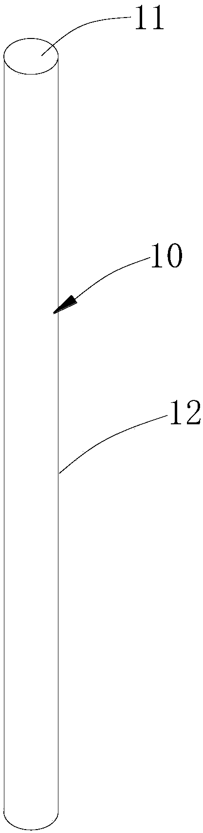
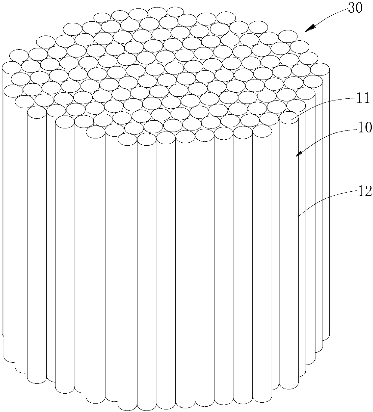
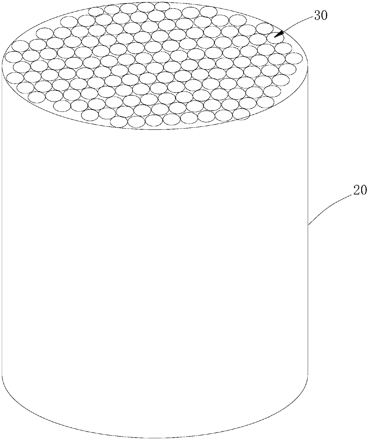
[0018] combine figure 1 As shown, the heat conduction structure in this embodiment can be used in the field of evaporation coating. The heat conduction structure 30 includes several heat conduction pipes 10, wherein each heat conduction pipe 10 is a tubular body with a hollow interior and an opening 11. The outer walls of the several heat conduction pipes 10 12 are bonded and fixed to each other to form a heat conduction structure 30 , and the radial cross-sectional shape of several heat pipes 10 bonded and fixed together is a grid shape. The heat pipe 10 is used to accommodate the material to ...


PUM


Abstract

The invention discloses a heat conduction structure. The heat conduction structure comprises a plurality of heat conduction pipes. Each heat conduction pipe is of a hollow tubular body with an opening. The outer walls of the multiple heat conduction pipes are mutually attached and fixed, and the shape of the section, in the radial direction, of the multiple attached heat conduction pipes is a gridshape. The invention further provides a heating and evaporating assembly. The heating and evaporating assembly comprises a crucible and the above heat conduction structure, and the shape and the sizeof the heat conduction structure are matched with the shape and the size of the crucible. The heat conduction structure is arranged in the crucible, and the outer walls of the heat conduction pipes on the outermost part of the heat conduction structure make contact with the inner wall of the crucible. According to the provided heat conduction structure and the provided heating and evaporating assembly, the heat conduction structure is formed by the multiple heat conduction pipes, a plurality of auxiliary evaporation bodies are formed, and disturbance among the auxiliary evaporation bodies canbe reduced; and the heat of the crucible wall adjacent to a heating source can be rapidly conducted into the crucible, and uniformity of the temperature field in the non-balance state is promoted.

Description

technical field [0001] The invention relates to the field of coating equipment, more specifically, to a heat conduction structure and a heating evaporation component. Background technique [0002] Evaporation coating is one of the technologies of vacuum PVD coating. Evaporation coating equipment is usually divided into vacuum chamber, vacuum acquisition system, thermal evaporation system, and electric control system. The thermal evaporation system consists of an evaporation container (evaporation crucible, evaporation boat, etc.), a resistance wire heater or other heating devices, a heat shielding system, and a heating temperature control system. The process puts the evaporation raw material in the crucible, and uses the heating mode in the vacuum environment to cause the solid-liquid-gas phase transition process of the coating raw material. The evaporation raw material is heated above the melting point to generate evaporation gas at the liquid surface or directly evaporate...

Claims


Application Information

Patent Timeline
Patent Type & Authority Applications(China)
IPC IPC(8): C23C14/26
CPCC23C14/26
Inventor 刘壮张撷秋杨世航黄俏俏
Owner SHENZHEN INST OF ADVANCED TECH
Why Eureka
Try Eureka