Damper for pantograph and method for adjusting maximum tensile damping force

A technology of dampers and pantographs, applied in the direction of shock absorbers, shock absorbers, liquid shock absorbers, etc., can solve the problems of easy loosening of the structure, unreliable maximum damping force of stretching, etc., and achieve the elimination of dimensional processing accuracy and Consistency, easy oil-spill problem solving, easy-to-achieve results

Pending Publication Date: 2018-03-23
ZHUZHOU LINCE GRP +1
View PDF7 Cites 5 Cited by
  • Summary
  • Abstract
  • Description
  • Claims
  • Application Information

AI Technical Summary

Problems solved by technology

Although the patent provides a scheme for adjusting the maximum damping force of the damper, in this scheme, spring valve discs are arranged on the end surface of the piston close to the chamber I of the cylinder and the end surface of the piston close to the

Method used


Image

  • Damper for pantograph and method for adjusting maximum tensile damping force
  • Damper for pantograph and method for adjusting maximum tensile damping force
  • Damper for pantograph and method for adjusting maximum tensile damping force

Examples


Embodiment Construction

[0033] The present invention will be further described below in conjunction with the accompanying drawings and specific embodiments.

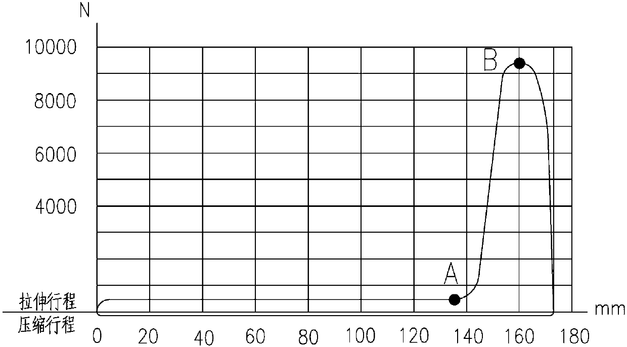
[0034] as attached figure 1 As shown, the tensile damping force and the compressive damping force of the pantograph damper involved in the present invention are very asymmetrical, and the damping force is required to maintain a relatively stable small damping force during the entire compression process, while the preceding Most of the stroke damping force needs to be kept at a relatively stable small damping force, and the damping force needs to increase rapidly in the following small part of the stroke, and a peak value appears.

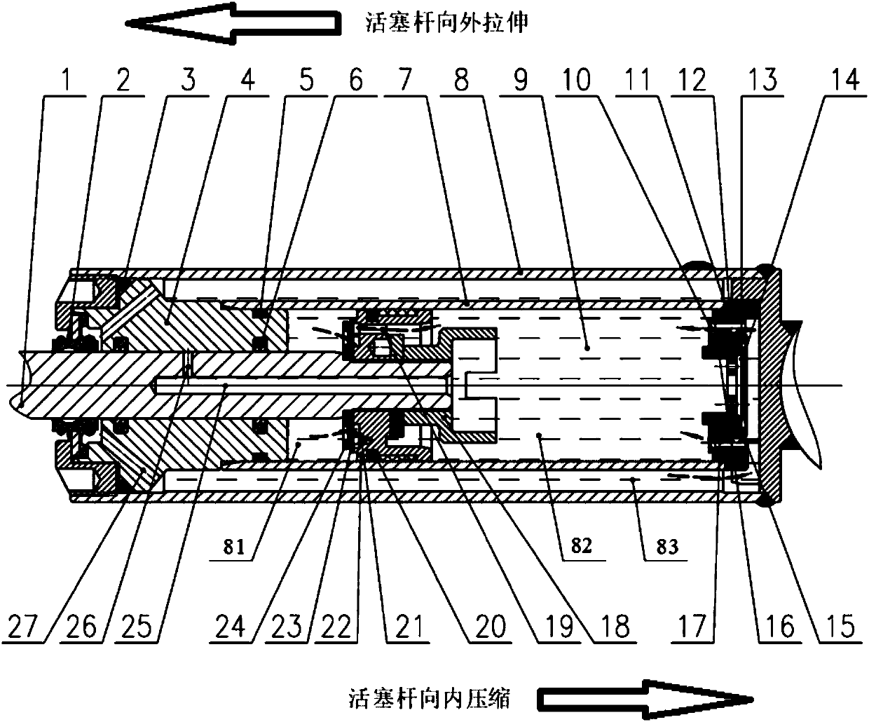
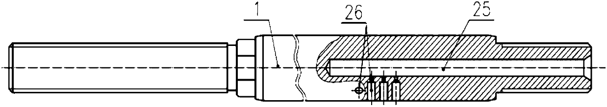
[0035] as attached Figure 2-5 As shown, a pantograph damper of this embodiment includes: oil storage cylinder 8, oil cylinder 7, guide assembly, piston rod assembly, hydraulic oil 9 and bottom valve assembly; guide assembly includes guide 4 and its Sealing structure, the sealing structure includes two static seali...


PUM

PropertyMeasurementUnit
Thicknessaaaaaaaaaa
Thicknessaaaaaaaaaa

Abstract

The invention provides a damper for a pantograph. The damper comprises an oil storage cylinder, an oil cylinder, a guide, a piston rod, a piston, hydraulic oil and a bottom valve seat, wherein a plurality of throttling holes are formed in the piston rod; one end of each throttling hole communicates with a through oil hole; the other end of each throttling hole is designed as an opening which facesthe exterior of the piston rod; the opening of each throttling hole can be exposed to the interior of a cavity I and/or is covered by the guide; at least two throttling holes are distributed at different positions along the axial direction of the piston rod; and a gasket is arranged between the inner end along the axial direction of the oil cylinder and the bottom valve seat, and used for adjusting the maximum tensile damping force in the outward tensile stroke of the piston rod. According to the damper provided by the invention, a conventional structure for adjusting the maximum tensile damping force through a nut, a spring and a valve plate is canceled and changed to a structure for adjusting the maximum tensile damping force by additionally mounting gaskets of different thicknesses. The damper is simple and feasible, and convenient to maintain.

Description

technical field [0001] The invention relates to a damping throttling and sealing device, in particular to a damper applied to pantographs of rail transit vehicles such as electric locomotives, urban rail vehicles, and EMUs. Background technique [0002] The pantograph is a key component of rail transit vehicles such as electric locomotives, urban rail vehicles, and EMUs. It is installed on the roof of rail transit vehicles. Teleported to the car for locomotive use. A pantograph usually includes: chassis, damper, bow lifting device, lower arm, bow assembly, lower guide rod, upper arm, upper guide rod, bow head, slide plate and bow air source control valve plate and other mechanisms, while the damper Installed between the base frame and the lower arm. The fluency of the pantograph collecting current from the catenary is related to the contact pressure, transition resistance, and contact area between the slide plate and the catenary, and depends on the interaction between the...

Claims


Application Information

Patent Timeline
IPC IPC(8): F16F9/19F16F9/34F16F9/36F16F9/32
CPCF16F9/19F16F9/3207F16F9/3214F16F9/3221F16F9/34F16F9/36
Inventor 陈文韬王三槐戴谋军吴忠发
Owner ZHUZHOU LINCE GRP
Why Eureka
Try Eureka