Supercharge Your Innovation With Domain-Expert AI Agents!

Liquid processing apparatus

A liquid treatment and liquid treatment technology, applied in the field of liquid treatment devices, can solve the problems without any disclosure and the like

Active Publication Date: 2018-03-23
TOKYO ELECTRON LTD
View PDF8 Cites 0 Cited by
  • Summary
  • Abstract
  • Description
  • Claims
  • Application Information

AI Technical Summary

Problems solved by technology

[0006] However, Patent Document 1 does not disclose any method for suppressing contamination of the substrate due to the aforementioned eddy current when mist or the like stays around the cup, etc.

Method used


Image

  • Liquid processing apparatus
  • Liquid processing apparatus
  • Liquid processing apparatus

Examples


Embodiment Construction

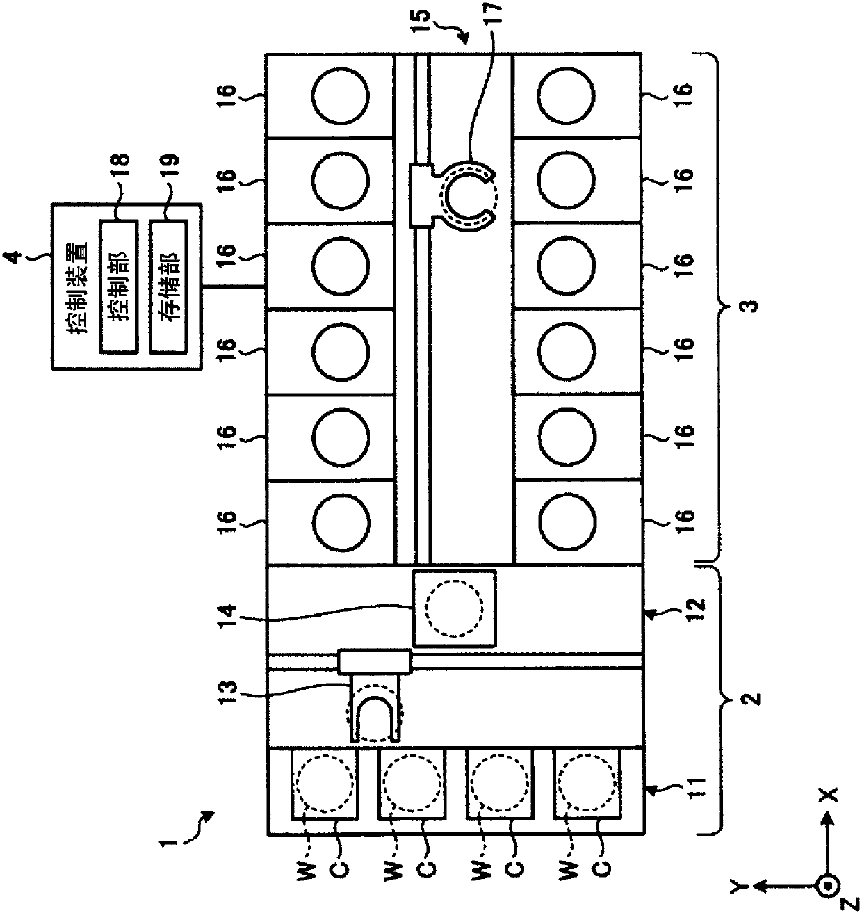
[0038] figure 1 It is a figure which shows the schematic structure of the substrate processing system of this embodiment. Hereinafter, in order to clarify the positional relationship, the X-axis, Y-axis, and Z-axis orthogonal to each other are defined, and the positive direction of the Z-axis is defined as the vertical upward direction.

[0039] Such as figure 1 As shown, a substrate processing system 1 has an input and output station 2 and a processing station 3 . The input and output station 2 and the processing station 3 are arranged adjacently.

[0040] The input / output station 2 has a carrier placement unit 11 and a transport unit 12 . A plurality of carriers C for accommodating a plurality of substrates, which are semiconductor wafers in this embodiment (hereinafter referred to as wafer W), in a horizontal state are placed on the carrier placement portion 11 .

[0041] The conveyance part 12 is provided adjacent to the carrier mounting part 11, and has the board|subs...


PUM


Abstract

The invention provides a liquid processing device capable of maintaining the atmosphere around a cup body in a clean state. The liquid processing device (16) supplies treatment liquid to a rotating substrate W for conducting liquid processing. Enclosure members (20, 23, 24) enclose, from outside of a cup body (50), a region surrounding the rotating substrate W and including an area over the cup body (50) that has an opening on the upper part thereof. A gas flow current forming section (21) forms gas flow current downward from over the cup body (50). A floor section (28) circumferentially blocks the space between the cup body (50)and the enclosure members (20, 23, 24). Exhaust ports (241 and 231) provided outside of the cup body (50) exhaust gas from a space that is over the floor section (28) and is surrounded by the enclosure members (20,23, 24) and the floor section (28).

Description

[0001] This application is a divisional application of an application with a filing date of September 12, 2014, an application number of 201410466264.6, and an invention title of "liquid processing device". technical field [0002] The present invention relates to a technique for exhausting a space for liquid processing a substrate. Background technique [0003] In a single-chip liquid processing unit (liquid processing device) that supplies various processing liquids to a semiconductor wafer (hereinafter referred to as a wafer) as a substrate for liquid processing, alkali, Acidic chemical solution to remove dust, natural oxides, etc. on the surface of the wafer. The chemical solution remaining on the surface of the wafer is removed by the rinsing solution, and when the supply of the rinsing solution is stopped while the wafer is kept rotating, the remaining rinsing solution is shaken off to obtain a dried wafer. Here, a recovery cup (cup body) for recovering the processing...

Claims


Application Information

Patent Timeline
Patent Type & Authority Applications(China)
IPC IPC(8): H01L21/67B08B17/00
CPCB08B17/00H01L21/67017H01L21/67051H01L21/6719
Inventor 胁山辉史伊藤规宏东岛治郎
Owner TOKYO ELECTRON LTD
Features
  • R&D
  • Intellectual Property
  • Life Sciences
  • Materials
  • Tech Scout
  • Unparalleled Data Quality
  • Higher Quality Content
  • 60% Fewer Hallucinations
Learn More