
Automotive RF male connector and female connector and connector assembly

A technology of male connectors and connectors, which is applied to parts, connections, and two-part connection devices of connection devices, etc., which can solve the problems of easy loosening of solder joints between RF antennas and PCB boards, unstable signal transmission, and small insertion force, etc. question

Pending Publication Date: 2018-03-23
深圳市百莲科技有限公司
View PDF0 Cites 2 Cited by
  • Summary
  • Abstract
  • Description
  • Claims
  • Application Information

AI Technical Summary

Problems solved by technology

[0002] The RF antenna for vehicles is mainly used for wireless transmission and reception of audio information, video information or data streams; at present, the RF antenna for vehicles is directly soldered to the PCB board during the assembly and connection process, and the head of the RF antenna is the welding position , when installing, directly solder the head of the RF antenna to the PCB board; although this method can achieve the purpose of connecting the RF antenna to the PCB board to transmit signals, however, due to the standard pull-out force of the RF antenna used in the vehicle The limitation of this welding method cannot meet the standard of pulling force of more than 8KG required by the vehicle RF antenna. During use, the welding point between the RF antenna and the PCB board is easy to loosen, and even the RF antenna falls off the PCB board. This will cause unstable signal transmission or even signal transmission failure, which will affect the use effect; in addition, this welding connection method cannot achieve the effect of small insertion force and large pulling force, resulting in inconvenient assembly and disassembly. it's not easy

Method used


Image

  • Automotive RF male connector and female connector and connector assembly
  • Automotive RF male connector and female connector and connector assembly
  • Automotive RF male connector and female connector and connector assembly

Examples


Embodiment approach

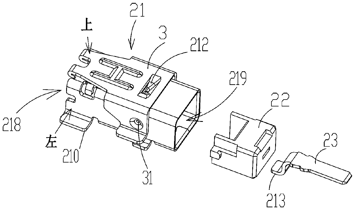
[0040] The present invention also provides a female connector, image 3 and Figure 4 Shown is an embodiment of a female connector, a female connector, including a female housing 21, a female plastic 22 and a female terminal 23, and one end of the female housing 21 is provided with a first socket for receiving a male connector. An opening 219, the left and right sides of the female base housing 21 are partially extended outward to form at least one first veneer 210, the first veneer 210 is perpendicular to the left and right sides, The first bonding panel 210 is used for bonding with the PCB board, thereby replacing the technology in which the wiring harness 9 is directly welded to the PCB board in the prior art; the front and rear ends of the female seat plastic 22 are connected, and the female seat The seat plastic 22 is set in the female seat shell 21; the female seat terminal 23 extends into the female seat plastic 22, the female seat terminal 23 is installed in the femal...


PUM


Abstract

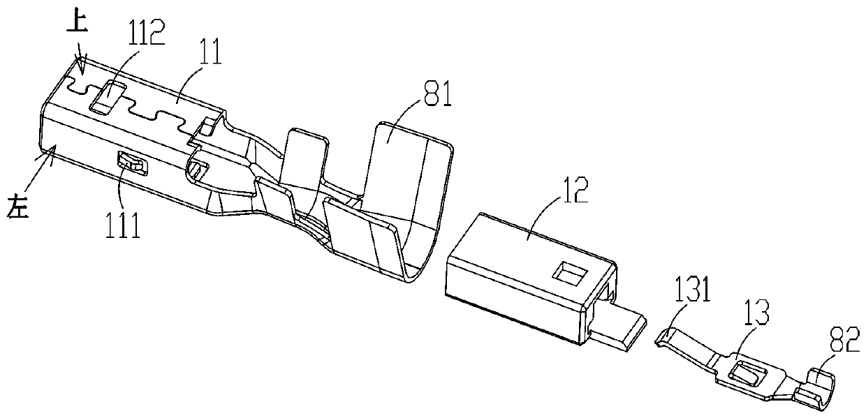
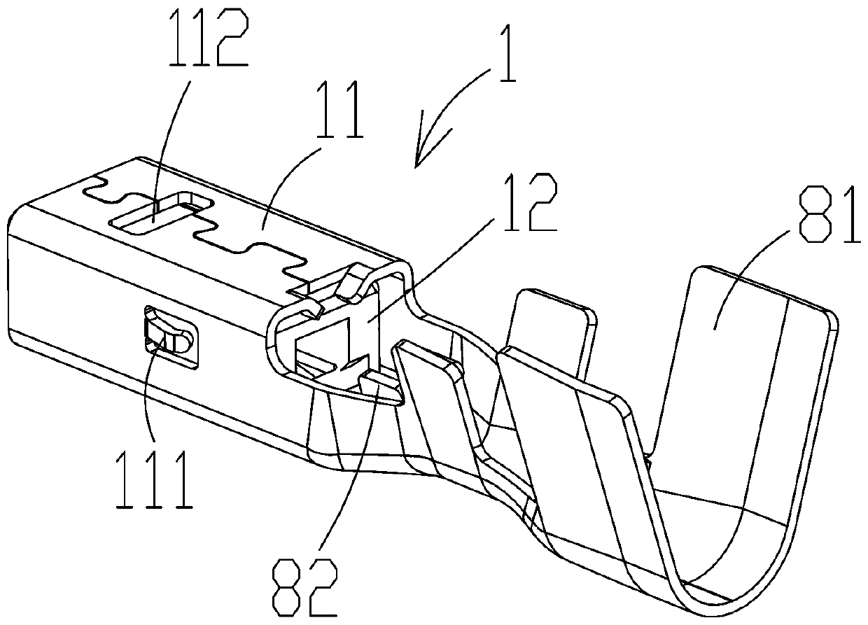
The invention discloses an automotive RF male connector and female connector and a connector assembly. The male connector comprises a male seat housing, male seat plastic and a male seat terminal, wherein a first U-shaped fixing structure for accommodating a wire harness and fixing the wire harness is arranged at one end of the male seat housing; the front end and the rear end of the male seat plastic are penetrated; the male seat plastic is arranged in the male seat housing; the male seat terminal stretches into the male seat plastic; a second U-shaped fixing structure for accommodating the wire harness and fixing the wire harness is arranged at one end, corresponding to the first U-shaped fixing structure, of the male seat terminal; the male seat terminal is electrically connected with awire core; and a first contact end which is used for being in contact with a female seat terminal and being electrically connected with the female seat terminal is arranged at the other end of the male seat terminal. The automotive RF male connector has the advantages that connection between an RF antenna and a PCB is more firm and the automotive RF male connector is small in insertion force, large in drawing force and more convenient to assemble and disassemble.

Description

technical field [0001] The invention relates to the field of connectors, in particular to a vehicle RF male connector, a female connector and a connector assembly. Background technique [0002] The RF antenna for vehicles is mainly used for wireless transmission and reception of audio information, video information or data streams; at present, the RF antenna for vehicles is directly soldered to the PCB board during the assembly and connection process, and the head of the RF antenna is the welding position , when installing, directly solder the head of the RF antenna to the PCB board; although this method can achieve the purpose of connecting the RF antenna to the PCB board to transmit signals, however, due to the standard pull-out force of the RF antenna used in the vehicle The limitation of this welding method cannot meet the standard of pulling force of more than 8KG required by the vehicle RF antenna. During use, the welding point between the RF antenna and the PCB board ...

Claims


Application Information

Patent Timeline
Patent Type & Authority Applications(China)
IPC IPC(8): H01R13/405H01R24/20H01R24/28
CPCH01R13/405H01R24/20H01R24/28
Inventor 杨四平王世明李宗穆
Owner 深圳市百莲科技有限公司
Learn More